
Power generation control device of idling stop vehicle

A power generation control and idling stop technology, applied in circuit devices, battery circuit devices, control systems, etc., can solve problems such as battery overcharging, reduced vehicle assembly workability, weight increase, etc., to prevent overcharging, relieve discomfort, The effect of maintaining degrees of freedom

Active Publication Date: 2013-09-25
HONDA MOTOR CO LTD
View PDF5 Cites 4 Cited by
  • Summary
  • Abstract
  • Description
  • Claims
  • Application Information

AI Technical Summary

Problems solved by technology

However, it is foreseeable that if the cable wires are thickened, the weight will increase, or the wiring bundle will be made stronger or the volume will increase, which will inevitably require a design change, or reduce the workability of the vehicle assembly.
On the other hand, if the target adjustment voltage is set uniformly high considering the voltage drop caused by the resistance of the harness, there is a possibility that the battery will be overcharged.

Method used


Image

  • Power generation control device of idling stop vehicle
  • Power generation control device of idling stop vehicle
  • Power generation control device of idling stop vehicle

Examples


Embodiment Construction

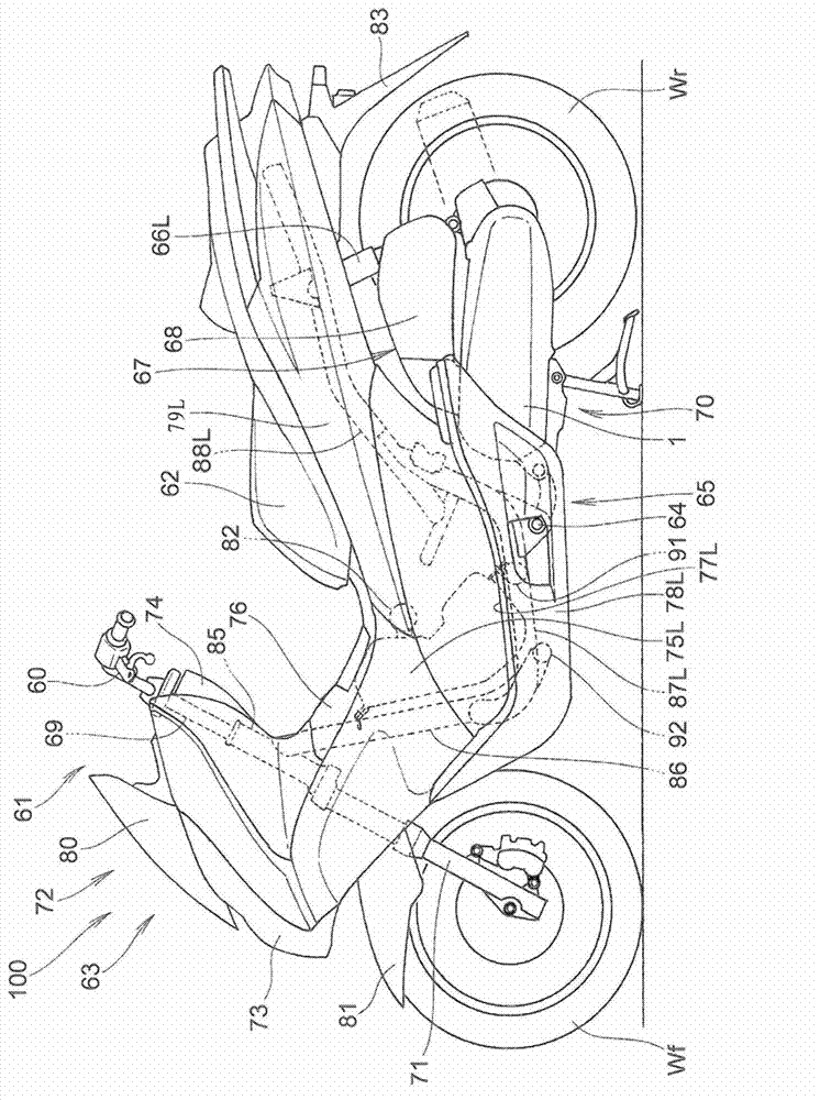
[0045] Hereinafter, embodiments of the present invention will be described with reference to the drawings. figure 1 It is a side view of a scooter type two-wheeled motor vehicle to which the vehicle power generation control device of the present invention is applied. In the present embodiment, an idling stop function that stops the engine when a predetermined stop condition is satisfied, and Restart the engine when the specified starting conditions are met.

[0046] The motorcycle 100 has: a front wheel Wf that is steerably supported by a steering system 61 including a handlebar 60; a unit swing type engine 1 that is arranged behind the front wheel Wf; and a rear wheel Wr that is arranged on the The rear of the engine 1 and driven by the engine 1; the seat 62 is provided between the front wheel Wf and the rear wheel Wr, and the motorcycle 100 is a saddle-riding type vehicle in which the driver sits on the seat 62 .

[0047] The motorcycle 100 has a frame 63, and a link mecha...


PUM


Abstract

The invention provides a power generation control device of an idling stop vehicle, which can constantly supply proper charging voltages without changing a current wire harness whether the charging residue of a battery is large or small. In a moment (t1), lag angular coordinate (theta x) power generation among gain control is started. In a moment (t2) when the lag angular coordinate (theta x) exceeds a switching threshold value (theta ref) and lasts for a designated voltage boost judging period (delta), voltage boost control starts in a moment (t3). The voltage boost control is performed in a way to simply gradually increase a target adjusting voltage (Vt) through an increase rate (delta V). Later in a moment (t6), decrease control on the lag angular coordinate (theta x) is started. In a moment (t8) when the lag angular coordinate (theta x) is lower than the switching threshold value (theta ref) and lasts for a voltage decrease judging period (delta), voltage decrease control is started in a moment (t10). The voltage decrease control is performed in a way to simply gradually decrease a target adjusting voltage (Vt) through a decrease rate (delta V).

Description

technical field [0001] The present invention relates to a power generation control device for an idling stop vehicle, and more particularly, to a power generation control device for an idling stop vehicle capable of solving the problem of insufficient charging caused by the reduction of the generated power due to the resistance of the wiring harness of the charging system, thereby reducing the charging voltage. Background technique [0002] As a vehicle power generator, a three-phase synchronous generator driven by an engine is known. The AC power generated by the three-phase synchronous motor is rectified by a three-phase full-wave rectifier, voltage-regulated, and charged to the battery. Patent Document 1 discloses a power generation control in which, in a system in which power generated by a generator driven by an engine is supplied to a battery and an electrical load, a drive circuit performs an advanced or retarded energization angle with respect to a stator coil. Powe...

Claims


Application Information

Patent Timeline
Patent Type & Authority Applications(China)
IPC IPC(8): H02P9/04H02J7/14
Inventor 大泽俊章永露敏弥小林正树加门邦人荻野和政
Owner HONDA MOTOR CO LTD
Learn More