Audio power amplifier and adjusting method thereof

A technology of audio power and adjustment method, applied in the field of audio power amplifier adjustment and audio power amplifier, can solve the problems of clipping suppression false turn-on, redundant noise, errors, etc., to reduce the cost of peripheral circuits, reduce redundant noise, and reduce design The effect of complexity

Active Publication Date: 2013-09-25
ACTIONS ZHUHAI TECH CO
View PDF6 Cites 10 Cited by
  • Summary
  • Abstract
  • Description
  • Claims
  • Application Information

AI Technical Summary

Problems solved by technology

[0014] 1. The existence of the preamplifier 20 will introduce unnecessary noise, and will also increase the cost of the peripheral circuit and increase the complexity of the design;
[0015] 2. There is a difference between the intermediate signal and the waveform of the digital audio signal finally output by the audio amplifier 10. Therefore, the preamplifier 20 only judges whether there is clipping in the output digital audio signal by detecting the intermediate signal, and determines with this When the clipping suppression is turned on, there will be certain errors, which will cause the clipping suppression to be turned on by mistake;
[0016] 3. After clipping is suppressed, the time to release the suppression is only determined with a fixed delay time, but the time to release the suppression is not accurately determined by detecting whether the clipping disappears. Therefore, it is easy to cause part of the clipping to be unable to be suppressed, for example , when the clipping duration exceeds the delay time, there will still be clipping that has not disappeared but is not suppressed after the release of the suppression
Therefore, the adjustment method used to realize the clipping suppression of the audio power amplifier 10 in the prior art will also cause the problems mentioned above to appear

Method used


Image

  • Audio power amplifier and adjusting method thereof
  • Audio power amplifier and adjusting method thereof
  • Audio power amplifier and adjusting method thereof

Examples


Embodiment Construction

[0050] In order to make the object, technical solution and advantages of the present invention clearer, the present invention will be further described in detail below with reference to the accompanying drawings and examples.

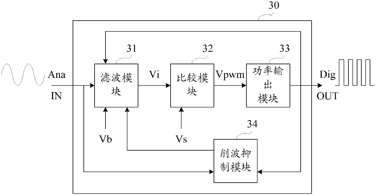
[0051] image 3 It is a schematic diagram of an exemplary structure of an audio power amplifier in an embodiment of the present invention.

[0052] See image 3 , the audio power amplifier 30 in the present embodiment includes: the filter module 31, the comparison module 32 and the power output module 33 that are serially connected in series between the audio input terminal IN and the audio output terminal OUT of the audio power amplifier 30, that is, sequentially connected in series The filter module 31, the comparison module 32, and the power output module 33 constitute the signal path of the audio power amplifier 30;

[0053] see you again image 3 , the audio power amplifier 30 in this embodiment further includes: a clipping suppression module 34...


PUM


Abstract

The invention provides an audio power amplifier and an adjusting method thereof. According to the audio power amplifier, clipping inhibition of the audio power amplifier is realized by adjusting self zero-frequency gain without the assistance of peripheral devices, so that unnecessary noise caused by the inducing of the peripheral devices is decreased, cost of peripheral circuits is decreased, and the complexity of design is decreased as well; furthermore, according to the audio power amplifier, output digital audio signal is detected to judge whether clipping exists in the digital audio signal or not, and the time of opening clipping inhibition through turning down zero-frequency gain is determined according to the judgment, so that error opening of the clipping inhibition caused by detecting error can be decreased; additionally, according to the audio power amplifier, whether the clipping already disappear or not is judged according to an input analog audio signal, and the time of releasing clipping inhibition through turning up zero-frequency gain is determined according to the judgment, so that the problem that the clipping can not be completely restrained caused by improper releasing and restraining time is avoided.

Description

technical field [0001] The invention relates to audio power amplification technology, in particular to an audio power amplifier with an analog audio signal as an input and a digital audio signal as an output and an adjustment method for the audio power amplifier. Background technique [0002] The function of the audio power amplifier is to amplify the input audio signal, and drive the passive acoustic components (such as speakers, earphones) to sound by outputting the amplified audio signal. [0003] According to different types of input and output audio signals (digital or analog), the audio power amplifier can adopt different working modes. Among them, the class D working mode is a common working mode. The audio power amplifier adopting this working mode takes analog audio signal as input and digital audio signal as output. The audio power amplifier mentioned in this article mainly refers to the audio power amplifier. [0004] figure 1 It is a schematic structural diagr...

Claims


Application Information

Patent Timeline
IPC IPC(8): H03F3/20H03G3/20
Inventor 唐晓
Owner ACTIONS ZHUHAI TECH CO
Why Eureka
Try Eureka