A monitoring device and method combining video calibration and electronic map

An electronic map and monitoring equipment technology, applied in the field of intelligent video monitoring, can solve the problems of security information and real-time dynamics that cannot be displayed intuitively, less information, and low efficiency, and achieve continuous tracking and monitoring, comprehensive correlation, and monitoring Wide field of view effect

Active Publication Date: 2017-09-19
ROPEOK TECHNOLOGY GROUP CO LTD
View PDF3 Cites 0 Cited by
  • Summary
  • Abstract
  • Description
  • Claims
  • Application Information

AI Technical Summary

Problems solved by technology

[0003] But the traditional electronic ground Figure 1 Generally, with the help of importing map files such as BMP and JPG, the form of coordinate points is generally used on the electronic map, and the actual video image can only be accessed after clicking the coordinate point. Generally, you can only browse videos one by one on the electronic map, which cannot be realized The synchronous browsing of videos from multiple regional cameras cannot intuitively display the security information and real-time dynamics around the monitoring point, and it is difficult to organically link the situations of many video surveillance images on the large screen. Real real-time dynamic information cannot be fed back on the electronic map
However, the electronic map's feedback on the regional orientation and objects comes from the accuracy and update cycle of the map. Therefore, the traditional electronic map technology has shortcomings such as less information, low efficiency, and slow update.

Method used


Image

  • A monitoring device and method combining video calibration and electronic map
  • A monitoring device and method combining video calibration and electronic map
  • A monitoring device and method combining video calibration and electronic map

Examples


Embodiment Construction

[0041] The present invention will be further described in detail below in conjunction with the accompanying drawings and embodiments.

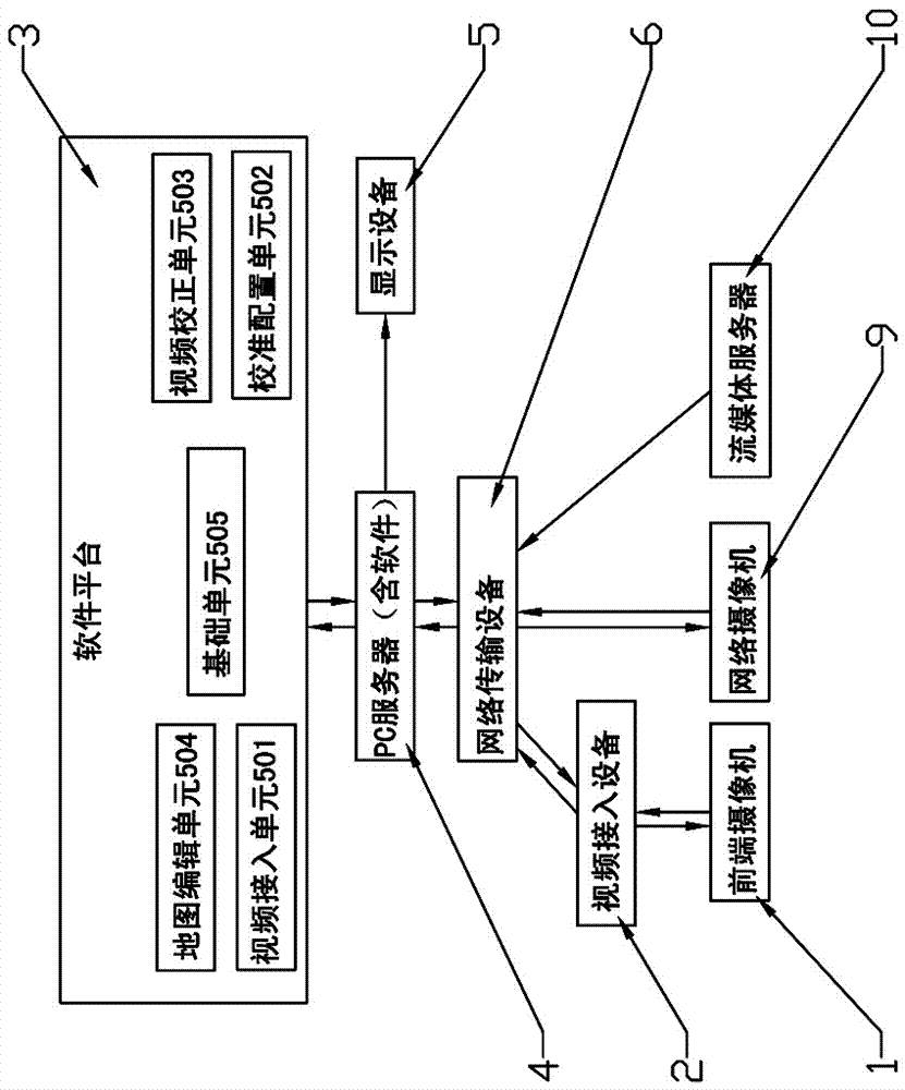
[0042] refer to figure 1 - Figure 5 As shown, it is an embodiment of the present invention, such as figure 1 As shown, the embodiment of the present invention provides a system structure diagram of a surveillance method that combines video calibration and electronic maps in video surveillance. The present invention includes: a front-end camera 1, a video access device 2, a software platform 3, and a PC server 4. Display device 5, network transmission device 6, etc.

[0043] Further: if the front-end camera 1 is an analog camera or a fiber optic camera, it must be connected to the network through an embedded hard disk video recorder or a video encoder (video server).

[0044] Further: the video access device 2 may be: network video surveillance equipment such as industrial control video storage equipment, embedded hard disk video recorder...


PUM


Abstract

A monitoring device that combines video calibration and electronic maps, including: a front-end camera connected to a video access device, connected to a network transmission device, and then connected to a PC server, and the PC server is connected to a software platform and a display device. The method includes: connecting the network video monitoring device Access to the software platform; open the software platform, add video access devices on the software platform; calibration: perform frame extraction on the single-channel video stream on the software platform, convert calculation and calibration, and form map and coordinate correspondence table 1; calibration configuration : The relationship table 1 is obtained through the calibration algorithm calculation to obtain the map and coordinate correspondence table 2 of all pixels in the video extraction frame; video correction: the video coordinate points are adjusted to the three-dimensional posture; repeat steps 203 and 204 to realize multiple videos The calibration and correction of the frame on the map, the traditional electronic map is simulated and reproduced, and the original virtual static picture is turned into a real-time dynamic video stream, which can effectively improve the overall monitoring and early warning decision-making of the entire video monitoring area.

Description

Technical field: [0001] The invention relates to the field of intelligent video monitoring, in particular to a monitoring device and method combining video calibration and electronic map. Background technique: [0002] Electronic maps are widely used in video surveillance systems due to their intuitive performance, rich functions, and sufficient information. By marking the positions of cameras and sensors on the map, it is convenient for users to accurately locate monitoring points. The innovative hot zone navigation function can extend the map to the interior of the building, and present information such as safety facilities, evacuation routes, and dangerous areas to users in a three-dimensional manner. Existing video surveillance management software generally has an electronic map function, which enables users to quickly browse video hotspots and quickly link video images for early warning on the electronic map. [0003] But the traditional electronic ground Figure 1 Ge...

Claims


Application Information

Patent Timeline
Patent Type & Authority Patents(China)
IPC IPC(8): H04N7/18G09B29/10
Inventor 孙申雨卢天发李仁杰陈延艺林敏
Owner ROPEOK TECHNOLOGY GROUP CO LTD
Why Eureka
Try Eureka