Method for controlling cusped magnetic field thruster plume divergent angle

A cusp magnetic field and thruster technology, which is applied in the field of controlling the plume divergence angle by the configuration of the magnetic interface of the cusp magnetic field thruster, can solve the problems such as the difficulty in controlling the plume divergence angle of the cusp magnetic field thruster, and achieve reduction Effect of Small Plume Divergence Angle

Active Publication Date: 2013-09-25
HARBIN INST OF TECH
View PDF5 Cites 18 Cited by
  • Summary
  • Abstract
  • Description
  • Claims
  • Application Information

AI Technical Summary

Problems solved by technology

[0003] The present invention proposes a method for controlling the plume divergence angle of a cusp magnetic field thruster in order to solve the problem of difficult control of the plume divergence angle of the cusp magnetic field thruster

Method used


Image

  • Method for controlling cusped magnetic field thruster plume divergent angle
  • Method for controlling cusped magnetic field thruster plume divergent angle
  • Method for controlling cusped magnetic field thruster plume divergent angle

Examples


specific Embodiment approach 1

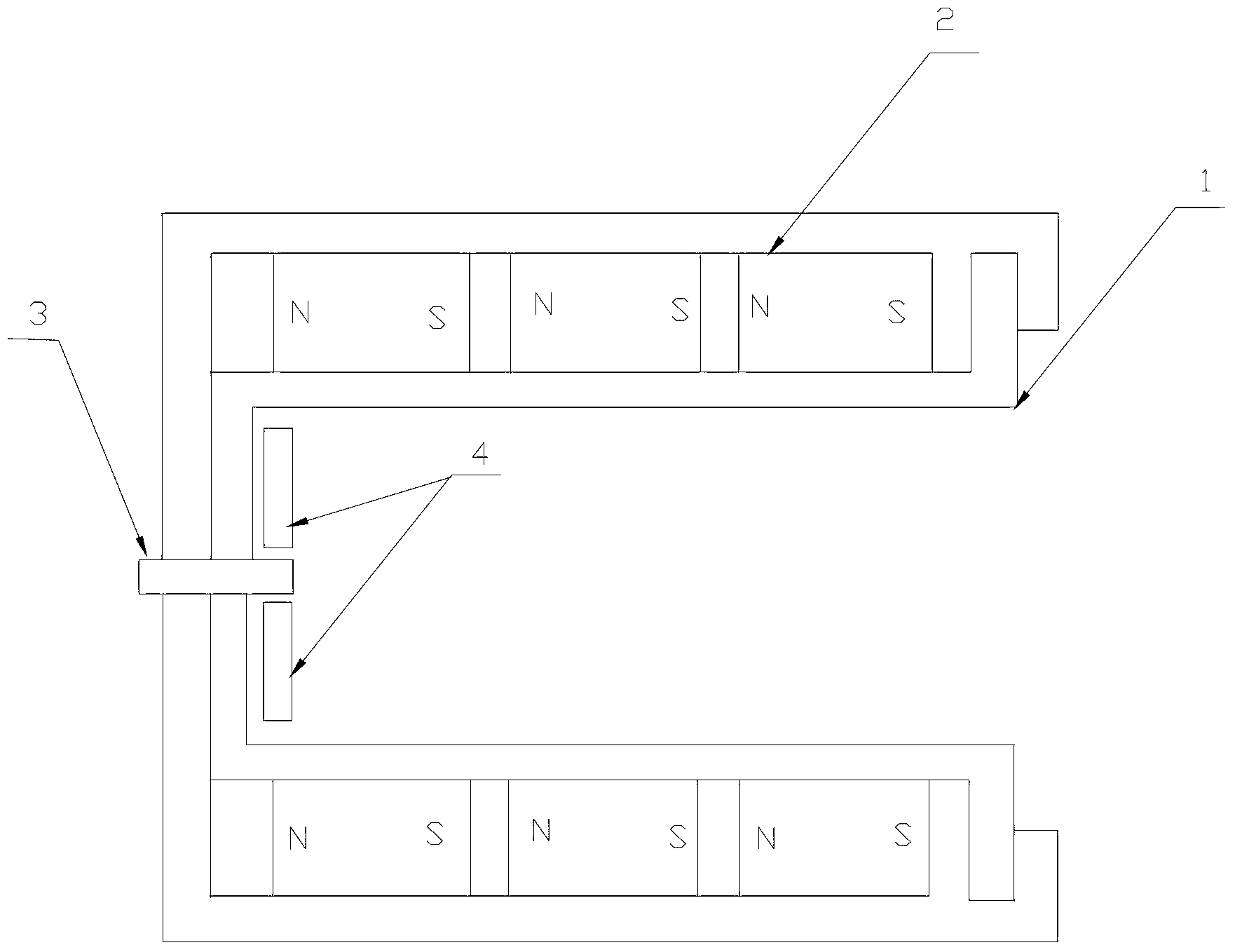
[0014] Specific implementation mode 1. Combination figure 1 , figure 2 , image 3 and Figure 4 Describe this embodiment, a method for controlling the plume divergence angle of a tangential magnetic field thruster described in this embodiment, the specific steps of the method are:

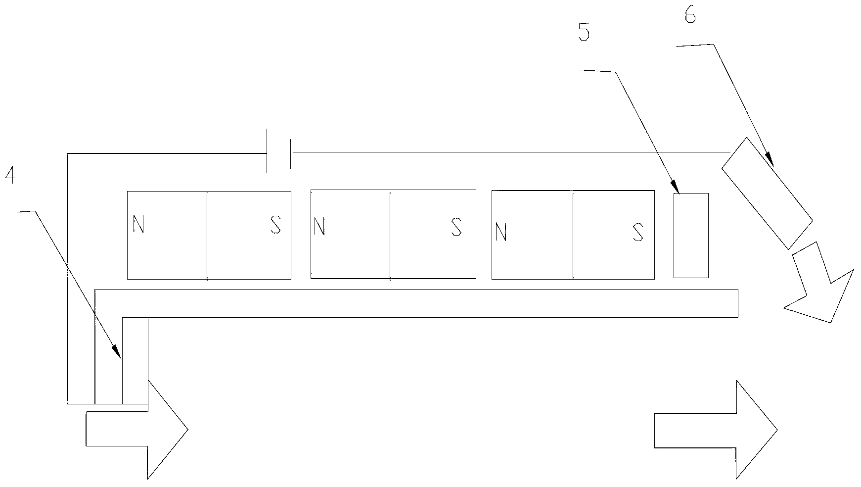
[0015] Step 1. Fix an annular plume control permanent magnet on the outside of the outermost permanent magnet at the outlet of the discharge channel of the tangential magnetic field thruster; The polarity of the permanent magnet is opposite;

[0016] Step 2: Ignite the cathode of the cusp magnetic field thruster, the cathode of the thruster emits electrons, and the electrons move to the inside of the discharge channel under the action of the electromagnetic field;

[0017] Step 3. Introduce xenon gas into the discharge channel of the cusp magnetic field thruster, and gradually increase the anode voltage with a step size n until the thruster ignites successfully; where n is a positive integer, ...

specific Embodiment approach 2

[0025] Specific Embodiment 2. This embodiment is a further description of a method for controlling the plume divergence angle of a tangential magnetic field thruster described in Embodiment 1. The annular plume control permanent magnet described in step 1 consists of a shaft It is composed of a permanent magnet magnetized radially and a permanent magnet magnetized radially.

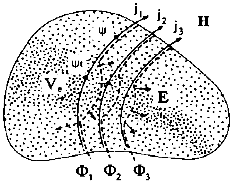
[0026] An annular axial permanent magnet is placed above the permanent magnet of the tangential magnetic field thruster, and its polarity is opposite to that of the permanent magnet of the tangential magnetic field thruster. The degree of convexity of the magnetic interface after the axial permanent magnet is installed is the same as that without installation Compared with the axial permanent magnet, the outer convex degree of the magnetic interface is significantly lower, so the installation of the permanent magnet ring with opposite polarity can effectively improve the configuration of the magnetic inter...

specific Embodiment approach 3

[0030] Specific Embodiment Three. This embodiment is a further description of a method for controlling the plume divergence angle of a tangential magnetic field thruster described in Embodiment Two. The axial length of the radially magnetized permanent magnet is less than or equal to 5mm .


PUM


Abstract

The invention provides a method for controlling a cusped magnetic field thruster plume divergent angle and relates to the method for controlling the plume divergent angle through cusped magnetic field thruster magnetic interface configuration to solve the problem that an existing cusped magnetic field thruster plume divergent angle is difficult to control. An annular plume control permanent magnet is fixedly arranged on the outer side of a permanent magnet which is arranged on the outmost face of a cusped magnetic field thruster channel outlet, a negative electrode of a thruster sends out electrons, xenon is filled into a discharging channel of the cusped magnetic field thruster, xenon ions are sprayed out of the discharging channel under the action of an electric field which is generated through self-consistence of the xenon ions and the electrons so that inward thrust is generated, annular plume control permanent magnets with different axial lengths and radial lengths are replaced so that the protruding extent of the magnetic interface configuration of the channel outlet can be reduced and the acceleration direction of the xenon ions can controlled, namely, the cusped magnetic field thruster plume divergent angle is controlled. The method for controlling the cusped magnetic field thruster plume divergent angle is suitable for controlling the cusped magnetic field thruster plume divergent angle.

Description

technical field [0001] The invention relates to a method for controlling the plume divergence angle by the configuration of the magnetic interface of a tangential magnetic field thruster Background technique [0002] The tangential magnetic field thruster is a new type of electric propulsion device. Its main structure is composed of a cylindrical ceramic discharge channel and an annular permanent magnet with opposite polarity. figure 1 As shown, it utilizes the electrons bound by the tangential magnetic field to ionize the inert gas working medium to form a high-speed directional plasma jet, thereby generating thrust. Compared with the traditional electric propulsion device, the tangential magnetic field thruster has become the most valuable electric propulsion device for engineering application and development due to its advantages such as wide thrust range, low working medium pollution, high efficiency, small wall erosion, and long service life. Since the plasma generated...

Claims


Application Information

Patent Timeline
Patent Type & Authority Applications(China)
IPC IPC(8): H05H1/10F03H1/00
CPCY02E30/10
Inventor 赵隐剑张亚男刘辉马成毓陈蓬勃孙国顺于达仁
Owner HARBIN INST OF TECH
Why Eureka
Try Eureka