Pulse optical fiber laser marking system

A fiber laser and pulse technology, applied in the laser field, can solve problems such as inability to automatically focus, and achieve the effect of automatic focus

Active Publication Date: 2013-09-25
SHENZHEN JPT OPTO ELECTRONICS CO LTD +1
View PDF10 Cites 2 Cited by
  • Summary
  • Abstract
  • Description
  • Claims
  • Application Information

AI Technical Summary

Problems solved by technology

[0012] The technical problem to be solved by the present invention is to provide a pulsed fiber laser marking system that can realize automatic focusing according to the posi

Method used


Image

  • Pulse optical fiber laser marking system
  • Pulse optical fiber laser marking system
  • Pulse optical fiber laser marking system

Examples


Embodiment Construction

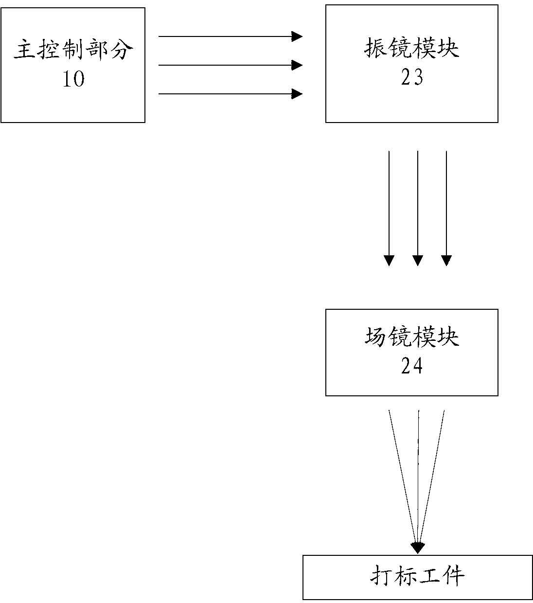
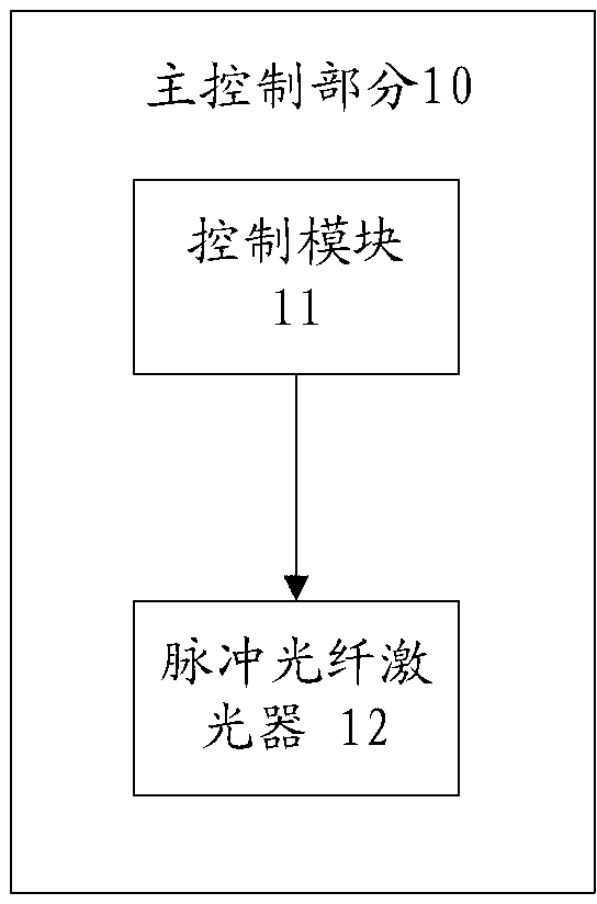
[0034] combine figure 1 , figure 2 , in Embodiment 1 of the pulsed fiber laser marking system of the present invention, the marking system is connected to a PC, and the marking system includes a main control part 10 and an output part 20, wherein the output part 20 includes: a position detection module 21 , drive module 22, galvanometer module 23 and field mirror module 24, wherein, position detection module 21 is used for real-time detection the distance of the surface of marking workpiece to detection point, and detection result is returned to main control part 10, for example, position The detection module can be a laser ranging module or an ultrasonic ranging module. The main control part 10 is used to calculate the displacement information that the galvanometer module 23 and the field mirror module 24 need to move according to the detection results, and generate a driving signal according to the displacement information, and is also used to receive and process the marki...


PUM


Abstract

A pulse optical fiber laser marking system comprises a master control part (10), a galvanometer module (23), a field lens module (24), a position detection module (21) and a drive module (22). The position detection module detects the distance from the surface of a workpiece to be marked as a detection point in real time. The master control part calculates displacement information about the galvanometer module and the field lens module needing to move according to the detection result, and generates a drive signal according to the displacement information. The master control part also produces a galvanometer control signal and a focusing control signal. The drive module drives the galvanometer module and the field lens module to move according to the drive signal. The galvanometer module controls a laser beam to deflect according to the galvanometer control signal. The field lens module focuses the deflected laser beam on the surface of the workpiece to be marked according to the focusing control signal.

Description

technical field [0001] The invention relates to the field of laser technology, in particular to a pulse fiber laser marking system. Background technique [0002] In 1960, American Maiman developed a ruby ​​laser at the Hughes Institute in California, which was the first laser in the world. The birth of the new laser technology makes the ancient subject of optics take an epoch-making step, and it is also one of the most important scientific and technological achievements in human history. In less than 50 years, lasers have been widely used in various fields of human life, including industrial processing, biomedicine, military, scientific research, measurement, etc. [0003] Compared with traditional solid-state and gas lasers, pulsed fiber laser is a relatively new type of laser. Its main advantages include: [0004] 1. The glass fiber does not need the strict phase matching of the incident pump light like the crystal, which is due to the wide absorption band caused by the ...

Claims


Application Information

Patent Timeline
IPC IPC(8): B41J2/435B41J3/00
CPCB23K26/048B23K26/03B23K26/0622B23K26/082B41J2/471
Inventor 刘猛成学平刘明赵崇光刘健黄治家
Owner SHENZHEN JPT OPTO ELECTRONICS CO LTD
Why Eureka
Try Eureka