Real-time laser automatic focusing device and method

An automatic focusing and laser technology, applied in installation, optics, optical components, etc., can solve problems such as large influence, complex device and method, and unsatisfactory focusing precision and accuracy, achieving a wide range of applications, simple device, focusing Precision adjustable effects

Inactive Publication Date: 2022-06-03
UNIV OF ELECTRONICS SCI & TECH OF CHINA
View PDF5 Cites 2 Cited by
  • Summary
  • Abstract
  • Description
  • Claims
  • Application Information

AI Technical Summary

Problems solved by technology

[0003] The earliest autofocus technology judges the focus state by changing the shape of the reflected light spot through a cylindrical lens and a four-quadrant detector, but this method is greatly affected by ambient light, and the focus precision and accuracy are not ideal
Other autofocus system devices and methods are also more complicated

Method used


Image

  • Real-time laser automatic focusing device and method
  • Real-time laser automatic focusing device and method
  • Real-time laser automatic focusing device and method

Examples


Embodiment 1

[0024] Embodiment 1: Implementation method of real-time laser autofocus device.

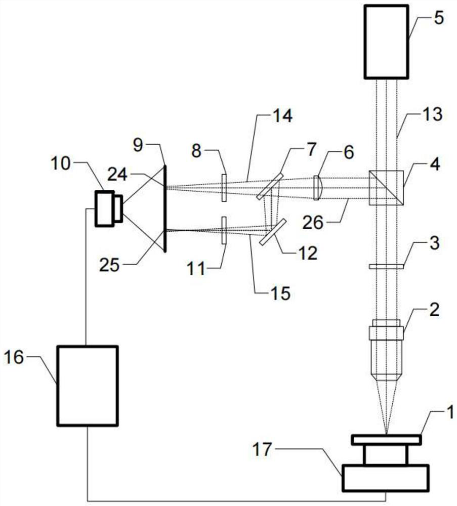
[0025] like figure 1 As shown, in the initial state, the moving platform 17 is located at point (X0, Y0, Z0), and the laser is in a focused state. When the motion platform moves according to the set trajectory, the position of the sample to be tested 1 relative to the microscope objective lens changes all the time. At the same time, the laser beam 13 passes through the polarization beam splitter 4, the 1 / 4 wave plate 3, and the microscope objective lens 2 in turn, and is reflected on the surface of the sample 1, and the reflected light then passes through the microscope objective lens 2, the 1 / 4 wave plate 3, and polarized beam splitter With mirror 4, the polarization state is changed so that the incident light and the reflected light are separated.

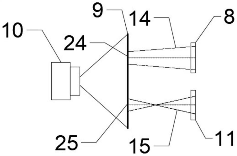
[0026] The reflected light beam 26 passes through the focusing lens 6, and the beam splitter 7 is divided into two beams of light 14 and 15. The...

Embodiment 2

[0031] Embodiment 2: A real-time laser autofocus method.

[0032] The image is collected by the image acquisition camera, and the camera can use CCD or COMS, etc. First, grayscale and binarize the collected images in turn, convert the grayscale value of the pixel in the grayscale range of 60-255 in the original image to 255, and then filter the binarized image through a low-pass filter High-frequency noise in the image, and then fill and repair the image to obtain a solid target image, then erode and expand the image to make the edges smoother, then mask the target image, and use the function to calculate the center position of the spot ;

[0033] Obtain the center positions of the two light spots, and calculate the width of the gray value in two arbitrary orthogonal directions passing through the center positions, and obtain the diameter of the binarized target image. During the real-time acquisition process, due to the light intensity of the light source Larger, the light ...

Embodiment 3

[0034] Embodiment 3: A real-time laser autofocus method.

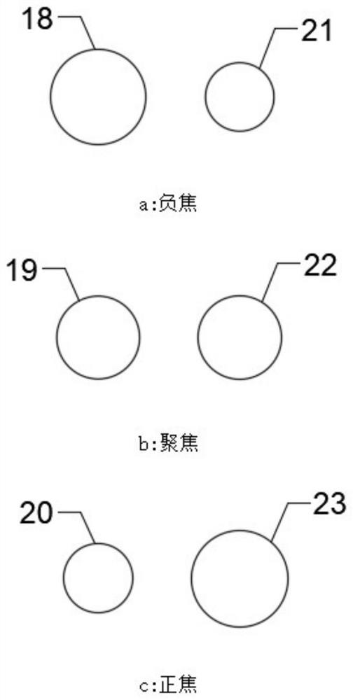
[0035] The specific image processing method is consistent with Embodiment 2, the difference is to calculate the area of ​​the two target images after the binarization process, the area can be calculated by the software's own algorithm or the area can be calculated by using the above-mentioned diameter; and according to the two spot areas The difference is used as a focusing error signal, which is used to control the Z-axis of the motion platform 17, so as to drive the sample 1 to be tested to move up and down to achieve focusing.


PUM


Abstract

The invention relates to a real-time automatic laser focusing device and method. The device comprises an optical module, an image acquisition module, an image processing module and a motion control module. Reflected light is divided into two beams, the sizes of light spots, at the same position, of the two beams of reflected light are made to be different by means of different optical paths, the laser focusing state is judged by means of the difference value of the diameters or the areas of the two light spots, and accordingly the Z-axis motion platform is controlled to achieve automatic focusing. The device has the advantages of being high in focusing precision, fast in response, large in adjustment range, adjustable in focusing precision and the like, is simple, is wide in application range, and can achieve a fast and real-time focusing function in laser focusing application.

Description

technical field [0001] The invention relates to the technical field of optical auto-focusing, in particular to a device and method for maintaining a focused state of laser light during a dynamic process. Background technique [0002] In the field of laser detection, the laser needs to be kept in focus at all times during the dynamic process, so that the entire equipment can operate normally. Therefore, a real-time laser autofocus technology and method are very important in laser applications. [0003] The earliest autofocus technology judged the focus state by changing the shape of the reflected light spot through a cylindrical lens and a four-quadrant detector, but this method was greatly affected by ambient light, and the focus precision and accuracy were not ideal. Other autofocus system devices and methods are also relatively complicated. Therefore, there is a need for an automatic focusing system with high focusing precision, fast response and simple structure. Cont...

Claims


Application Information

Patent Timeline
Patent Type & Authority Applications(China)
IPC IPC(8): G02B7/28
CPCG02B7/282
Inventor 吕杰张凯陈力
Owner UNIV OF ELECTRONICS SCI & TECH OF CHINA
Why Eureka
Try Eureka