Power transmission device for vehicle

A technology for transmitting device and driving force, applied in the direction of fluid drive clutch, non-mechanical drive clutch, clutch, etc., can solve the problem of limited application parts, and achieve the effect of improving reliability, realizing axial size, and improving compactness

Inactive Publication Date: 2013-09-25
AISIN AW CO LTD
View PDF6 Cites 3 Cited by
  • Summary
  • Abstract
  • Description
  • Claims
  • Application Information

AI Technical Summary

Problems solved by technology

[0008] Therefore, the above-mentioned leakage oil recovery device is a large-scale device that requires the space between the clutch cover and the cylinder housing sealed by the first sealing member outside the above-mentioned isolating elastic member. The application site is also limited

Method used


Image

  • Power transmission device for vehicle
  • Power transmission device for vehicle
  • Power transmission device for vehicle

Examples


Embodiment Construction

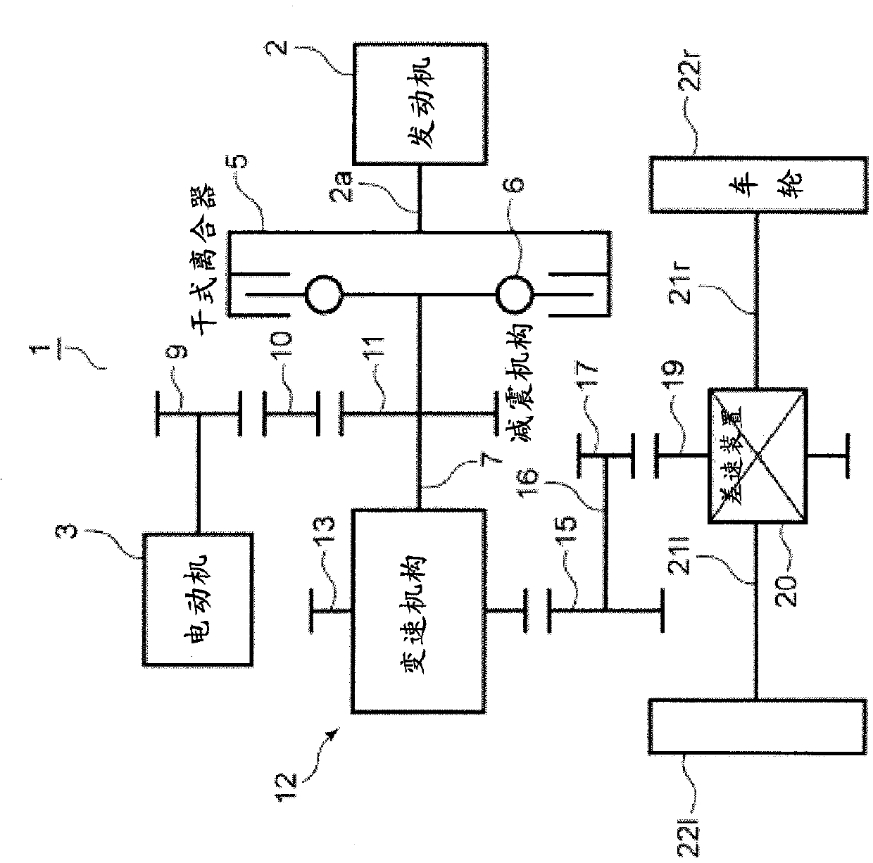
[0032] Next, the driving force transmission device for a vehicle of the present invention will be described based on the drawings. The driving force transmission device for the vehicle is applied as a single-motor type hybrid driving device 1, such as figure 1 As shown, the internal combustion engine 2 and the electric motor 3 are provided as the driving source. The output shaft 2a of the engine 2 is connected to the input shaft 7 via a dry clutch 5 and a damper spring 6. The rotor of the electric motor 3 is connected to the gear 11 provided on the input shaft 7 via the output gear 9 and the idler gear 10.

[0033] The rotation of the input shaft 7 is transmitted to the counter transmission gear 13 after being shifted by the transmission mechanism 12, and is also transmitted to the counter shaft 16 via the counter driven gear 15. The rotation of the countershaft 16 is transmitted to the differential device 20 via the gear 17 and the differential mount gear 19, and then is transm...


PUM


Abstract

Oil leaking from a hydraulic actuator for actuating a dry type clutch is prevented from permeating into a dry space where the dry type clutch is disposed. A space (57) formed by a piston rear side of the hydraulic actuator (50), a connection plate (56), and a cylinder part (51) is sealed with a first seal part (55) and a second seal part (59). Oil leaking from a piston (52) to a hydraulic oil chamber (50a) is stored in the space (57) and is returned to a wet space (W) formed in a case (25a) through an oil passage (61).

Description

Technical field [0001] The present invention relates to a driving force transmission device for a vehicle that transmits power from a drive source such as an engine or a motor to wheels through a clutch and a transmission device, and in detail relates to a dry clutch that transmits power from the drive source to the input shaft of the transmission device The structure of the hydraulic brake. Background technique [0002] As is well known, in a hybrid drive device that uses an engine and an electric motor as the drive source, the rotor of the electric motor is connected to the input shaft of the transmission, and a dry clutch is arranged between the input shaft and the engine to start with the electric motor for driving. The above engine device. [0003] The dry clutch interposed between the input shaft of the transmission device and the engine is arranged in a non-lubricated dry space, is energized into a constantly engaged state, and is released by supplying hydraulic pressure to...

Claims


Application Information

Patent Timeline
Patent Type & Authority Applications(China)
IPC IPC(8): F16D25/08
CPCF16D25/0635F16D25/087F16D2300/08F16D2300/26
Inventor 糟谷悟鬼头昌士关祐一高桥佑介
Owner AISIN AW CO LTD
Why Eureka
Try Eureka