Scanning bed

A technology of scanning bed and bed frame, applied in the field of scanning bed, can solve the problems of increasing measurement structure, inaccurate measurement results, complexity, etc., and achieve the effect of ensuring effectiveness and improving reliability

Inactive Publication Date: 2013-10-02
NEUSOFT MEDICAL SYST CO LTD
View PDF7 Cites 7 Cited by
  • Summary
  • Abstract
  • Description
  • Claims
  • Application Information

AI Technical Summary

Problems solved by technology

Therefore, although a dynamometer can be installed on the bed frame of the scanning bed or the fulcrum of the bed board to measure the patient's weight, it is often caused by the complexity of the judgment conditions such as the position of the human body and the bed board position, and the deformation of the bed board during the suspension stay. The result is inaccurate; in addition, due to the movement requirements of the s...

Method used


Image

  • Scanning bed
  • Scanning bed
  • Scanning bed

Examples


Embodiment 1

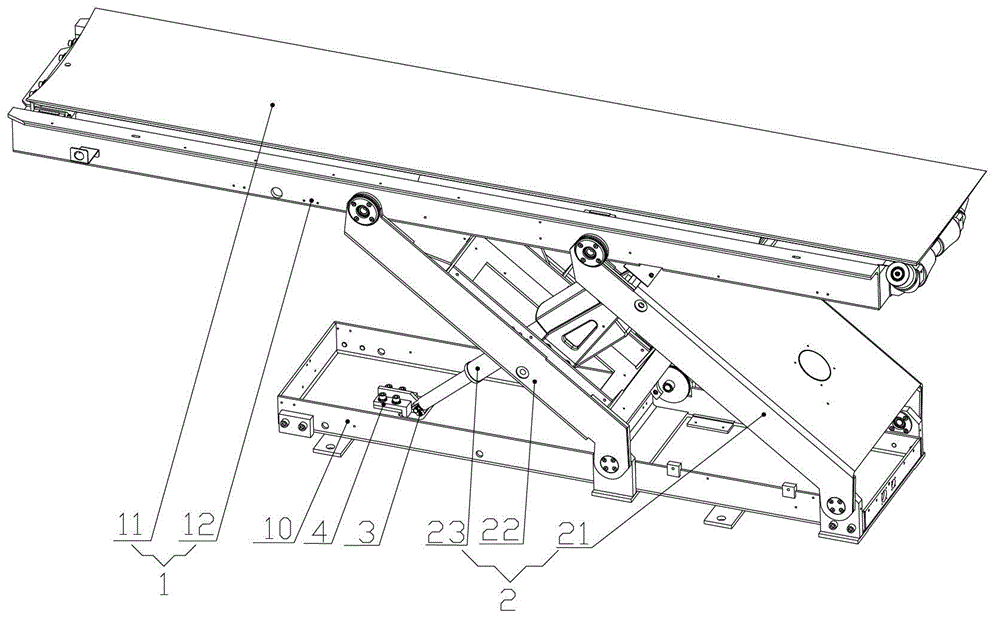
[0058] Such as Figure 1-3 As shown, in the first specific embodiment, the scanning bed includes a bed base 10, and the lifting assembly 2 may include a first swing rod 21, a second swing rod 22 and a driving support rod 23, and the first swing rod 21 and the second swing rod The rods 22 are arranged parallel to each other, one end of the two is hinged to the bed frame 1, and the other end is fixedly connected to the bed base 10, the swing of the first swing rod 21 and the second swing rod 22 can drive the bed frame 1 to lift or translate; drive the support Rod 23 can be set as the form of driving telescopic cylinder, which has a telescopic end and a fixed end, and is hinged with the first swing rod 21 or the second swing rod 22 with its telescopic end, and its fixed end is fixedly connected with the bed base 10, and drives The support rod 23 is connected to the force-measuring component 3 through its fixed end; since the first swing rod 21 and the second swing rod 22 are both...

Embodiment 2

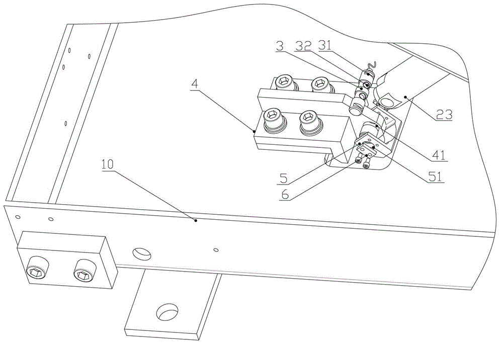
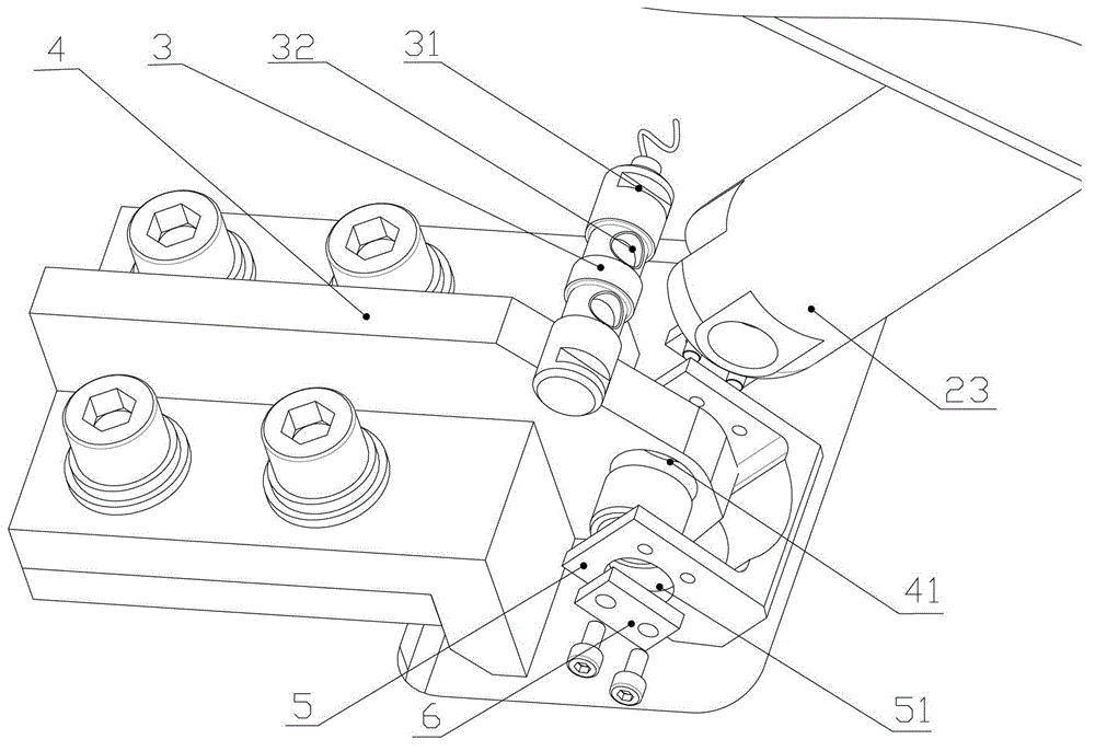
[0068] Please refer to Figure 5-Figure 6 , Figure 5 It is a schematic diagram of the assembly and disassembly of the force-measuring component and the driving support rod in the second specific embodiment of the scanning bed provided by the present invention; Figure 6 for Figure 5 Schematic diagram of the assembly of the middle force measuring part and the driving support rod.

[0069] In the second specific embodiment, the load-measuring component 3 can be a cantilever load cell with a strain gauge, and the cantilever load cell is hinged to the fixed end of the drive support rod 23, and the axis line of the drive support rod 23 is perpendicular to The strain gauge of the force-measuring component 3; the gravity of the patient acts on the driving support rod 23, and then is transmitted to the strain gauge of the force-measuring component 3 through the driving support rod 23, causing deformation of the strain gauge, thereby measuring the supporting force of the bed frame ...

Embodiment 3

[0074] Please refer to Figure 7 and Figure 8 , Figure 7 It is a schematic diagram of assembly and disassembly of the scanning bed provided by the present invention in the third specific embodiment; Figure 8 for Figure 7Schematic diagram of the assembly of the middle force measuring part and the driving support rod.

[0075] In the third specific embodiment, the force-measuring component 3 of the present invention can also be an S-type force-measuring sensor with strain gauges, please refer to Embodiment 2 for specific settings.

[0076] At this point, the base 4 can be set to a capping structure, such as Figure 7 and Figure 8 As shown, the base 4 has a gland 42, the gland 42 can be covered on the force-measuring component 3, and the gland 42 is fixedly connected to the bed base 10 through screws and other connecting pieces, so that the vertical direction of the force-measuring component 3 positioning, such as Figure 7 and Figure 8 shown.


PUM


Abstract

The invention provides a scanning bed which is capable of measuring the weight of a patient accurately. The scanning bed comprises a bedstead used for supporting the body of the patient, a lifting assembly used for driving the bedstead to operate, and a dynamometric component connected with the lifting assembly and used for detecting the supporting force applied to the bedstead by the lifting assembly. Due to the fact that the supporting force applied to the bedstead by the lifting assembly is related to the position of the patient and the position change of the bedstead, the connection between the lifting assembly and the dynamometric component enables the force measured by the dynamometric component to reflect the weight condition of the patient more truly and more accurately. According to the scanning bed, the change of the supporting force applied to the bedstead by the lifting assembly can be detected through the dynamometric component regardless of the position of the patient on the bedstead, the height of the bedstead and the horizontal position of the bedstead, the weight of the patient is then obtained combining with relevant data of the bedstead, and measuring accuracy is high.

Description

technical field [0001] The invention relates to the technical field of medical machinery, in particular to a scanning bed capable of measuring a patient's body weight. Background technique [0002] Usually, in the actual working process of large-scale medical imaging diagnostic equipment, the weight of the patient has important reference value for the arrangement of subsequent scanning measurements, the motion process of the scanning table and the judgment of the motion interference relationship between other components. However, current large-scale medical equipment, such as scanning beds for CT, MRI, and PET-CT, also known as patient beds and scanning stands (collectively referred to as scanning beds in this article), do not have a weighing function. [0003] In the prior art, the hospital beds capable of measuring body weight are mainly designed for patients with limited mobility and have a simple weighing function, so as to monitor the change of the patient's body weight...

Claims


Application Information

Patent Timeline
IPC IPC(8): A61B6/04A61B5/055G01G19/44
CPCA61B6/0407A61B6/032A61B6/037G01G19/52G01G19/445A61B5/055
Inventor 于军曹燕杰
Owner NEUSOFT MEDICAL SYST CO LTD
Why Eureka
Try Eureka