Microtube sensor for physiological monitoring

A technology of sensors and microtubes, which is applied in the direction of micro sensors, sensors, and the measurement of the properties and forces of piezoresistive materials, etc., which can solve the problem of limiting the design and integration of operating elements, limiting scalability and reproducibility, complex production processes, etc. problem, achieve sensitive force measurement, increase wearability, and reduce electronic components

Active Publication Date: 2019-12-06
NAT UNIV OF SINGAPORE
View PDF5 Cites 3 Cited by
  • Summary
  • Abstract
  • Description
  • Claims
  • Application Information

AI Technical Summary

Problems solved by technology

However, conventional silicon-based devices and many conductive materials are mechanically rigid and brittle
To overcome this, some methods deposit conductive layers of carbon nanotubes, nanoparticles, nanowires, and 2D materials onto stretchable substrates, resulting in overall mechanical deformability.
Composite materials require conventional fabrication methods such as transfer printing, electroless or electrodeposition, and screen printing, which typically limit the design and integration of operating elements in a planar environment
Furthermore, in many cases, the complex structure of the sensor requires a more expensive and complex production process, limiting scalability and reproducibility

Method used


Image

  • Microtube sensor for physiological monitoring
  • Microtube sensor for physiological monitoring
  • Microtube sensor for physiological monitoring

Examples


example 1

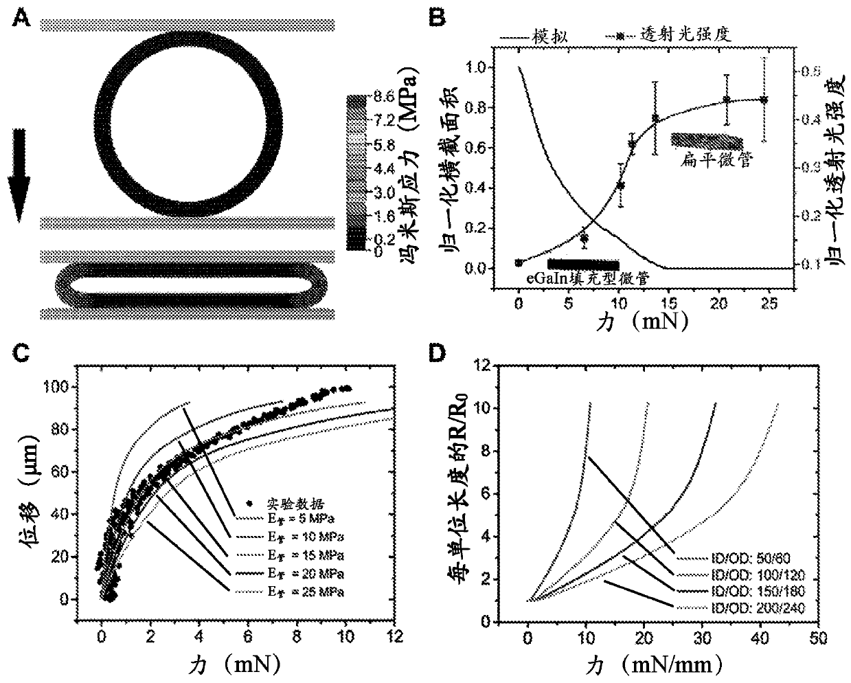
[0098] Example 1 - Finite Element Analysis:

[0099] Finite element modeling of the microtubule tactile sensor was performed using ABAQUS CAE for 2D plane strain and 3D analysis, depending on the geometry of the top tooth pitch (ie, the crosshead that compresses the microtubule). Due to the symmetry, one-half and one-quarter models were built for 2D plane strain and 3D analysis, respectively. Select the general static analysis mode, in which a hard and frictionless contact is established between the top tooth pitch and the outer surface of the upper half of the microtubule, the bottom plate and outer surface of the lower half of the microtubule, and the inner surface of the microtubule. Use mixed and linear elements with reduced order integration for contact analysis. The pipe wall is divided into 6 layers in the region of high stress near the mid-plane and into 4 layers in other regions. Assuming that flexible polydimethylsiloxane (PDMS) is elastic, [10] And Poisson's rati...

example 2

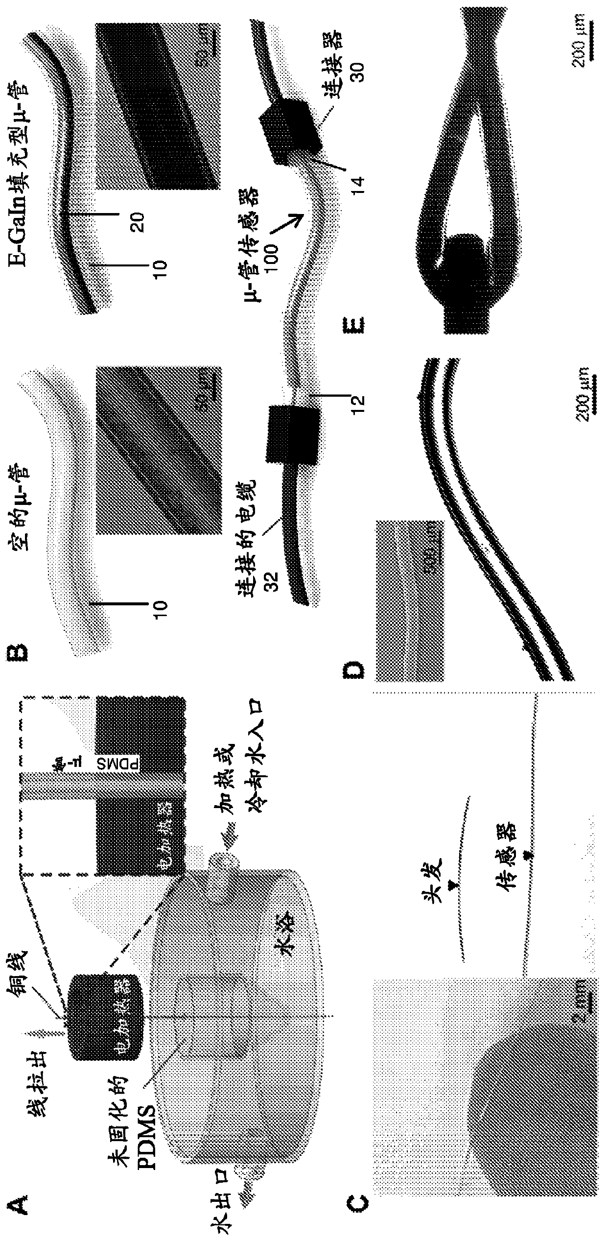
[0100] Example 2 - Device Design and Fabrication:

[0101] To fabricate microtubes, first dip a wire (e.g., wire) vertically into a 10:1 (w / w) mix of freshly mixed PDMS base and curing agent (e.g., 10:1 by weight of Sylgard 184 Silicon resin elastomer base and Sylgard 184 silicone elastomer curing agent). Pull the wire from the PDMS cell using a rotary motor at a speed of 2 mm / s to 4 mm / s. Simultaneously, hot water at ~100 °C was added to the surrounding PDMS pool to initiate PDMS curing. Solidification was further performed by hot air at ~95°C in a cylindrical heating device while the wire was drawn vertically above the liquid level. To maintain the optimum viscosity of PDMS for uniform coating around the wire, cold water can be added around the PDMS pool to prolong the curing time. Next, the metal wires were stripped during a sonication process in acetone solution, which washed away the unreacted elastomer curing agent and caused a slight swelling of the polymer, thereby ...

example 3

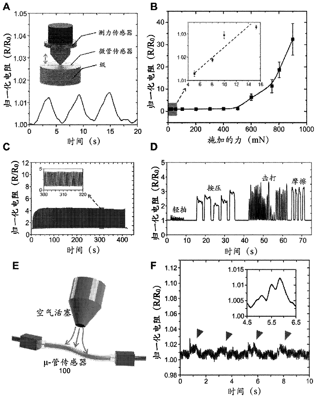
[0102] Example 3 - Pressure Sensing, Durability and Mechanical Differentiation:

[0103] A universal load machine (5848 MicroTester from Instron, Norwood, MA) was used to subject the liquid-based microtube tactile sensor to a compression ramp-hold-release load of 10 mN to 100 mN, as in Figure 3A Shown schematically. The ramp and release rate were set at 5 mm / min. The electrical response of the tactile sensor under different load applications was continuously monitored and recorded at 20 Hz using a custom data logging microprocessor.


PUM

PropertyMeasurementUnit
lengthaaaaaaaaaa
thicknessaaaaaaaaaa
lengthaaaaaaaaaa

Abstract

A soft, flexible micro-tube sensor and associated method of sensing force are described. A liquid metallic alloy is sealed within a micro-tube as thin as a strand of human hair to form the physical force sensing mechanism. The sensor is hardly distinguishable with the naked eye, and can be used for the continuous bio-monitoring of physiological signals, such as unobtrusive pulse monitoring. Also described is a method of fabricating the micro-tube sensor and wearable devices incorporating one or more micro-tube sensors.

Description

[0001] related application [0002] This application claims the benefit of U.S. Provisional Application No. 62 / 465,002, filed February 28, 2017. The entire teachings of the above applications are incorporated herein by reference. Background technique [0003] In recent years, the focus on flexible electronics has led to tremendous progress in soft and wearable sensors. Compared with rigid sensors, flexible, stretchable, and bendable sensors have shown great potential in health monitoring, soft robotics, electronic skin, and prosthetics. Elastic mechanical properties are key factors to enable wearable and imperceptible skin-to-skin contacts for in situ monitoring. However, conventional silicon-based devices and many conductive materials are mechanically rigid and brittle. To overcome this, some approaches deposit conductive layers of carbon nanotubes, nanoparticles, nanowires, and 2D materials onto stretchable substrates, resulting in overall mechanical deformability. Compo...

Claims


Application Information

Patent Timeline
Patent Type & Authority Applications(China)
IPC IPC(8): G01L1/18G01L1/22A61B5/024G01L5/10G01N27/06
CPCG01N27/06A61B5/02007A61B5/02108A61B5/02444A61B5/1038A61B5/6807A61B2562/0261A61B2562/028G01L1/20G01L1/245
Inventor 杨裕全奚望余龙腾林水德
Owner NAT UNIV OF SINGAPORE
Why Eureka
Try Eureka