Gas solubility jet flow generator

A generation device and gas-soluble technology, applied in the field of jet flow, can solve the problems of large water consumption of jet flow, low energy utilization rate, complex device structure, etc., and achieve the effect of high jet flow speed, promoting uniform gas-liquid mixing, and uniform gas-liquid mixing.

Inactive Publication Date: 2013-10-02
WUHAN UNIV OF SCI & TECH
View PDF8 Cites 2 Cited by
  • Summary
  • Abstract
  • Description
  • Claims
  • Application Information

AI Technical Summary

Problems solved by technology

[0004] (1) Small jet pressure, poor working effect and low efficiency;
[0005] (2) The energy consumed is large and the energy utilization rate is low when realizing a large jet impact force;
[0006]

Method used


Image

  • Gas solubility jet flow generator

Examples


Embodiment 1

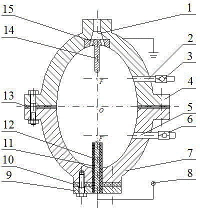
[0030] An aerosol jet generating device. Such as figure 1 As shown, the device consists of the generator upper hemisphere 4 and the generator lower hemisphere 7 fixedly connected by bolts to form a hollow ellipsoid; an intermediate sealing ring 13 is provided between the generator upper hemisphere 4 and the generator lower hemisphere 7, and the generator upper hemisphere 4 And the length ratio of the semi-major axis and the semi-minor axis of the lower hemisphere 7 of the generator is (1.2~2.0)︰1.

[0031] The end of the long semi-axis of the upper hemisphere 4 of the generator is provided with an upper boss, and the center of the upper boss is provided with a jet nozzle 1, the center line of the jet nozzle 1 coincides with the long semi-axis of the upper hemisphere 4 of the generator, and the port of the jet nozzle 1 The shape of the inner wall of the upper hemisphere 4 of the generator is successively a circular hole, a truncated cone hole and a reaming hole. The negative...

Embodiment 2

[0040] An aerosol jet generating device. Such as figure 1 As shown, the device consists of the generator upper hemisphere 4 and the generator lower hemisphere 7 fixedly connected by bolts to form a hollow ellipsoid; an intermediate sealing ring 13 is provided between the generator upper hemisphere 4 and the generator lower hemisphere 7, and the generator upper hemisphere 4 And the length ratio of the semi-major axis and the semi-minor axis of the lower hemisphere 7 of the generator is (2.0~2.5)︰1.

[0041] The end of the long semi-axis of the upper hemisphere 4 of the generator is provided with an upper boss, and the center of the upper boss is provided with a jet nozzle 1, the center line of the jet nozzle 1 coincides with the long semi-axis of the upper hemisphere 4 of the generator, and the port of the jet nozzle 1 The shape of the inner wall of the upper hemisphere 4 of the generator is successively a circular hole, a truncated cone hole and a reaming hole. The negative...


PUM

PropertyMeasurementUnit
Wall thicknessaaaaaaaaaa
Diameteraaaaaaaaaa
Cone angleaaaaaaaaaa

Abstract

The invention relates to a gas solubility jet flow generator. According to the technical scheme, a jet flow nozzle (1) is arranged on the end portion of a semi-major axis of an upper semisphere (4) of the generator. A negative electrode (14) is embedded into a counterbore of the jet flow nozzle (1) through a negative electrode base. 6-8 negative electrode jet flow holes (15) are formed in the negative electrode base in a central symmetry mode. A through hole is formed in the end portion of a semi-major axis of a lower semisphere (7) of the generator, one end of a positive electrode (12) penetrates through the through hole and is located in the lower semisphere (7) of the generator, and the other end of the positive electrode (12) is fixed in a central through hole of an end cover (9) and is connected with a positive pole of a high-voltage pulse power supply (8). The distance between the top of the positive electrode (12) and a central point O of a hollow oval sphere and the distance between the top of the negative electrode (14) and the central point O of the hollow oval sphere are equal. The central line of an air inlet (2) is perpendicular to the corresponding semi-major axis, and the central line of the air inlet (2) and the corresponding semi-major axis intersect at a focal point F of central line of the air inlet (2). The central line of a water inlet (5) is perpendicular to the corresponding semi-major axis, and the central line of the water inlet (5) and the corresponding semi-major axis intersect at a focal point F' of central line of the water inlet (5). The gas solubility jet flow generator has the advantages of being simple in structure, high in jet flow speed, large in power, low in energy consumption, saving in water and capable of conveniently adjusting jet flow pressure.

Description

technical field [0001] The invention belongs to the technical field of jet flow, and in particular relates to an aerosol jet flow generating device. technical background [0002] At present, water jet technology has been widely used in the fields of cleaning, breaking rocks, and improving metal surface properties. Traditional high-pressure water jets have high requirements for power equipment and pipelines, and at the same time have low energy efficiency, large water consumption, and high use costs. "A Vertical Jet Generator" (CN200910111049.3), which adopts the method of staggered arrangement of upper and lower circular strip electrodes in pairs, avoids the requirement of a high-pressure pump for the jet, and can conveniently adjust the jet intensity; "Hydropulse cavitation jet "Generating device" (CN201010141190.0) is a generating device that uses self-excited oscillating nozzles to generate cavitation jets. This device changes the flow field at the bottom of the well and ...

Claims


Application Information

Patent Timeline
IPC IPC(8): B05B5/053
Inventor 高全杰夏志勇汪朝晖汤泉军廖振方张豪
Owner WUHAN UNIV OF SCI & TECH
Why Eureka
Try Eureka