
Cereal homogenizing and collecting device

A technology of agglomeration device and grain, which is applied in solid separation, separation of solids from solids by air flow, chemical instruments and methods, etc. Impact force, guaranteed operation, avoid crushing or cracking effect

Active Publication Date: 2013-10-02
山东聚阳智能装备有限公司
View PDF6 Cites 7 Cited by
  • Summary
  • Abstract
  • Description
  • Claims
  • Application Information

AI Technical Summary

Problems solved by technology

The advantage of this air separator for light miscellaneous grains is that it slows down the impact force when the material falls, and improves the effect of light miscellaneous removal. Its disadvantage is that the equalizing tray does not have a channel for separating the materials, and the materials tend to accumulate more in one direction. Affect the impurity removal effect in this direction, and the materials thrown out by the uniform material pan will collide with the grain and miscellaneous separation cylinder, which will easily cause the crushing of the materials and reduce the output

Method used


Image

  • Cereal homogenizing and collecting device
  • Cereal homogenizing and collecting device
  • Cereal homogenizing and collecting device

Examples


Embodiment 1

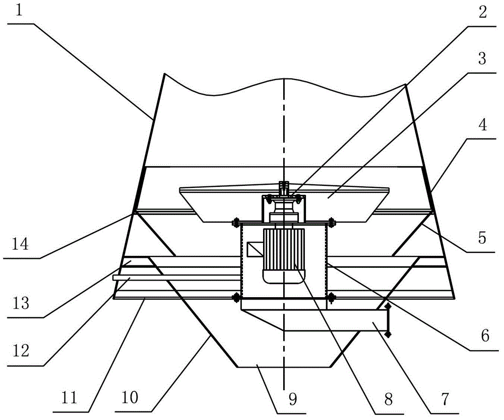
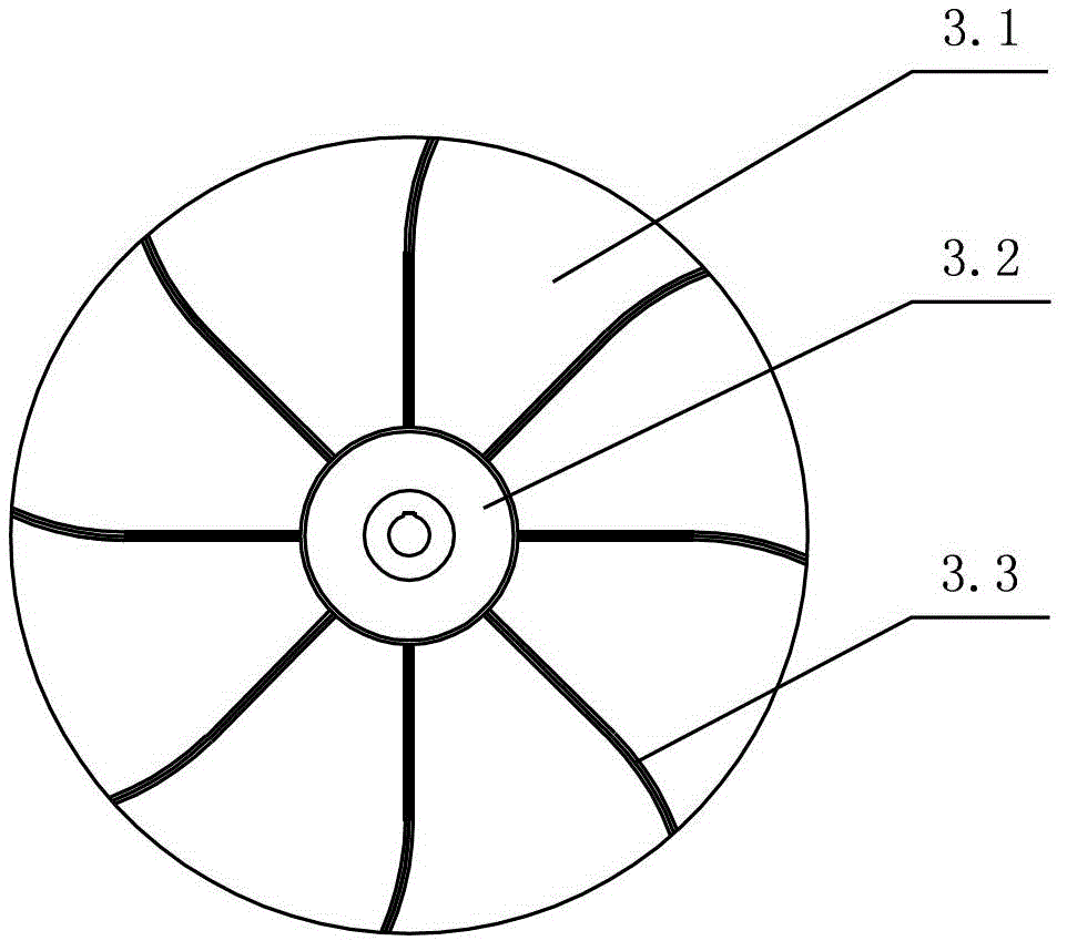
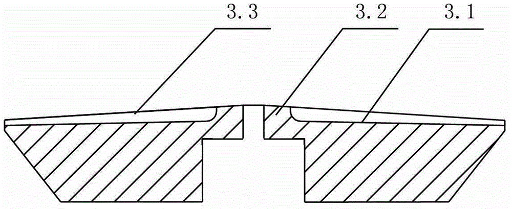
[0030] Examples of the present invention Figure 1~4 As shown, the rotating disk 3 is included, and the rotating disk 3 is arranged in the housing 1. The middle part of the rotating disk 3 is higher than the edge, and there is a circular protrusion 3.2 in the middle, and the bottom of the rotating disk 3 is a circular protrusion 3.2 from the edge to the middle. An upwardly inclined curve, the upper surface of the circular protrusion 3.2 is an inclined downward curve from the center to the edge, the fan blade 3.3 is arranged on the rotating disk 3, the circular protrusion 3.2 is fixedly connected with one end of the fan blade 3.3, and the outer edge is aligned Flat, the other end of the fan blade 3.3 extends to the edge of the rotating disk 3, the fan blade 3.3 is distributed on the upper surface of the rotating disk 3 in a divergent shape, and the fan blade 3.3 is a curved section from the middle of the rotating disk 3 to the edge of the rotating disk 3 in the same direction, ...

Embodiment 2

[0032] Such as Figure 5 As shown, the second collecting hopper 10 is connected to the housing 1 through the strip plates 15 arranged at intervals, and four strip plates can be arranged symmetrically, which can not only provide support for the second collecting hopper 10, but also ensure the smoothness of the winnowing channel .

Embodiment 3

[0034] Such as Figure 6 As shown, embodiment 1 is applied to a small winnowing machine. A feeding pipe 17 is arranged directly above the rotating disk 3. The feeding pipe is fixed on the housing 1. The upper end of the housing 1 is provided with an air suction port. The air suction port 16 is connected to an exhaust fan or light Miscellaneous processing equipment provides wind power for winnowing. The lower end of the shell 1 is fixed with a ring-shaped reinforcing plate 18 to stabilize the support of the shell. The feeding port is connected to the next process equipment.

[0035] work process:

[0036]Under the action of the suction fan at the air suction port 16 or the light miscellaneous treatment equipment, the air in the casing 1 flows upwards, and the outside air enters the casing through the air inlet and the discharge port at the connection between the second collecting hopper 10 and the casing 1. Inside the body, it enters the winnowing area formed by the rotating ...


PUM


Abstract

The invention relates to a cereal homogenizing and collecting device applied to a cereal winnowing machine, and belongs to the field of grain machinery. The device comprises a shell and a rotary disc, wherein the rotary disc is arranged in the shell, and the middle part of the rotary disc is higher than the edge. The rotary disc is an upward inclined curve from the edge to the middle part. The rotary disc is provided with fan blades which are scattered and distributed on the upper surface of the rotary disc. A motor is connected to the axis of the rotary disc, and a cereal collecting structure is arranged below the rotary disc. According to the device provided by the invention, cereals are uniformly distributed in a winnowing area, so that the residence time of cereals in the winnowing area is prolonged and the edulcorating efficiency is greatly improved, and the edulcorating rate is improved to 85% from original 70%. The cereals uniformly enter into a cereal colleting funnel to avoid blocking, so that the edulcorating system operates smoothly. The cereals are collided with the shell flexibly to prevent cereal particles from being crushed or cracked due to impact, so that the cereal winnowing output is improved.

Description

technical field [0001] The invention relates to a grain homogenizing and collecting device applied to a grain winnowing machine, belonging to the field of grain machinery. Background technique [0002] When large-scale winnowing and cleaning equipment removes impurities, there are disadvantages that the grain is fed too quickly so that the light impurities are pressed by the material, and the light impurities are not cleaned sufficiently. Sometimes the material enters the tuyeres below and it is easy to cause blockage. Moreover, there are few small-scale grain air separation and cleaning equipment suitable for farmers or grain stations at present, and the existing grain air separation systems are mostly used for large-scale air separation equipment, which is not suitable for the application of small equipment. [0003] Patent No. 201010272671.5 discloses a light miscellaneous grain separator. The grain miscellaneous separation chamber is designed to be fixedly installed on t...

Claims


Application Information

Patent Timeline
IPC IPC(8): B07B11/02B07B11/06B07B7/083
Inventor 史希水于效林张德喜
Owner 山东聚阳智能装备有限公司
Learn More