

Mechanical micro-feeding knife rest for KDP crystal ultra-precise flying cutting machining machine tool
A technology for processing machine tools and feed tool holders, which is applied to stone processing equipment, fine working devices, and work accessories. Easy to adjust precisely, high stability, avoid interference effect
- Summary
- Abstract
- Description
- Claims
- Application Information
AI Technical Summary
Problems solved by technology
Method used
Image

Examples
specific Embodiment approach 1
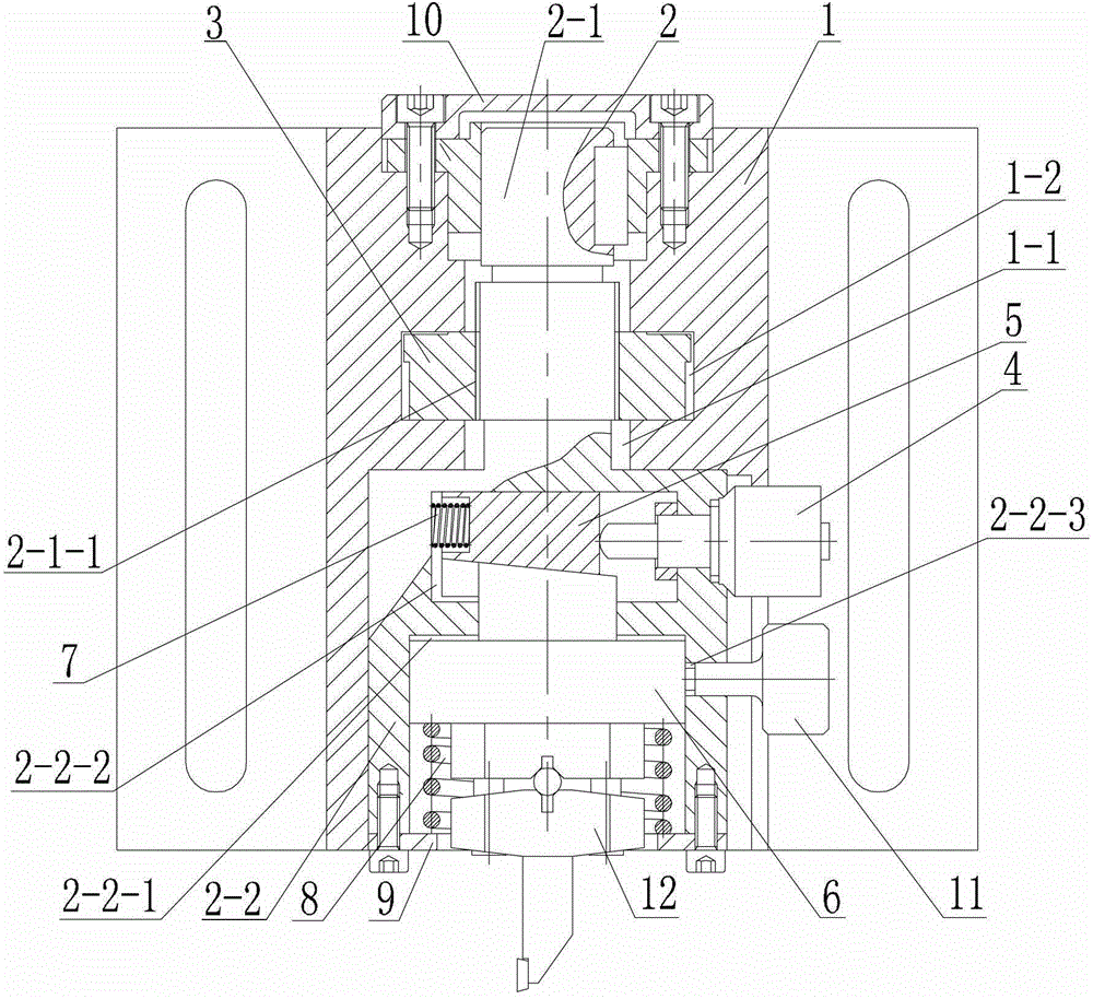
[0012] Specific implementation mode one: combine figure 1 Explain that a mechanical micro-feed tool holder for KDP crystal ultra-precision fly-cutting machine tools in this embodiment includes a tool holder housing 1, a feed shaft 2, a coarse adjustment nut 3, a differential head 4, an active wedge 5, Driven wedge 6, return spring 7, support spring 8, end cover 9, knife rest loam cake 10, locking screw pin 11 and knife clamp block 12, the middle part of knife rest housing 1 is along the vertical direction of knife rest housing 1 The shaft hole 1-1 is processed in the direction, and the middle part of the shaft hole 1-1 is processed with a nut installation groove 1-2, and the shaft hole 1-1 is connected with the nut installation groove 1-2, and the feed shaft 2 includes a small shaft 2- 1 and the large shaft 2-2, the small shaft 2-1 and the large shaft 2-2 are fixedly connected as one, and the small shaft 2-1 and the large shaft 2-2 are coaxially arranged, and the small shaft 2...
specific Embodiment approach 2
[0013] Specific implementation mode two: combination figure 1 Note that the feed function of this embodiment is divided into two parts: coarse adjustment and fine adjustment. The coarse adjustment part adopts the screw nut mechanism, and the fine adjustment part adopts the method of driving the inclined plane mechanism by the differential head, and the two are arranged in series as a whole.
[0014] Such a design can increase the feeding range of the tool holder, improve the feeding resolution and feeding accuracy. Other compositions and connections are the same as in the first embodiment.
specific Embodiment approach 3
[0015] Specific implementation mode three: combination figure 1 Note that the return spring 7 is a cylindrical helical compression spring, and the support spring 8 is a cylindrical helical compression spring or a Belleville spring.
[0016] Such a design is beneficial to reduce the overall size of the knife holder. Other compositions and connections are the same as those in Embodiment 1 or Embodiment 2.
PUM
| Property | Measurement | Unit |
|---|---|---|
| Division value | aaaaa | aaaaa |
| Surface roughness value | aaaaa | aaaaa |
| Graduation | aaaaa | aaaaa |
Abstract
Description
Claims
Application Information