
Shield cutter head driving device with cam ring motor

A technology of driving device and shield cutter head, which is applied in mining equipment, earthwork drilling, tunnels, etc., can solve the problems of complex transmission type, high cost, and high precision requirements of processing and manufacturing technology, and achieve simple transmission mechanism and simple manufacturing process , the effect of improving competitiveness

Active Publication Date: 2013-10-02
SHANGHAI TUNNEL ENG CO LTD +2
View PDF12 Cites 5 Cited by
  • Summary
  • Abstract
  • Description
  • Claims
  • Application Information

AI Technical Summary

Problems solved by technology

These two types of cutter head drive devices have similar structural types, but the transmission type is relatively complicated, and the manufacturing process requires high precision and high cost.
Moreover, because my country's domestic manufacturing industry is relatively backward compared with developed countries in Europe and the United States, the degree of localization of main bearings, oil motors, and reducers is not high, and they often need to be imported from abroad, making the cost of domestically produced cutter head drives high.

Method used


Image

  • Shield cutter head driving device with cam ring motor
  • Shield cutter head driving device with cam ring motor
  • Shield cutter head driving device with cam ring motor

Examples


Embodiment Construction

[0018] The present invention will be further described below in conjunction with the accompanying drawings and specific embodiments.

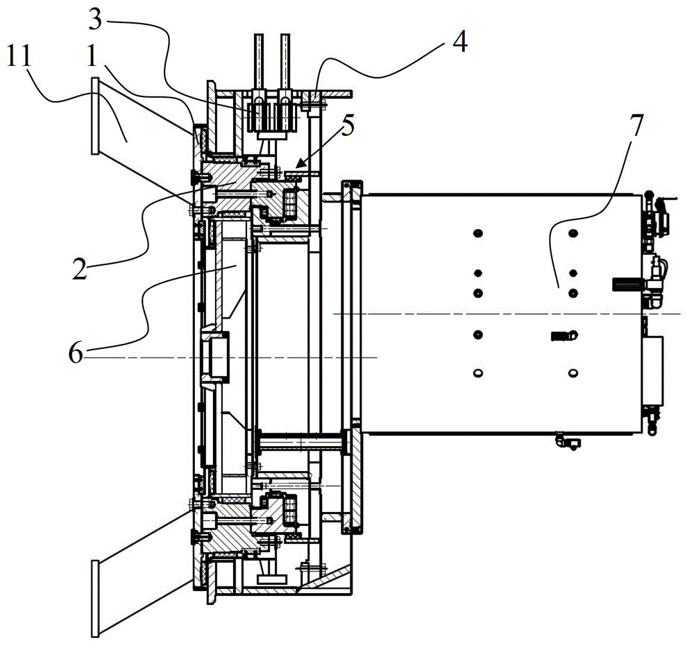
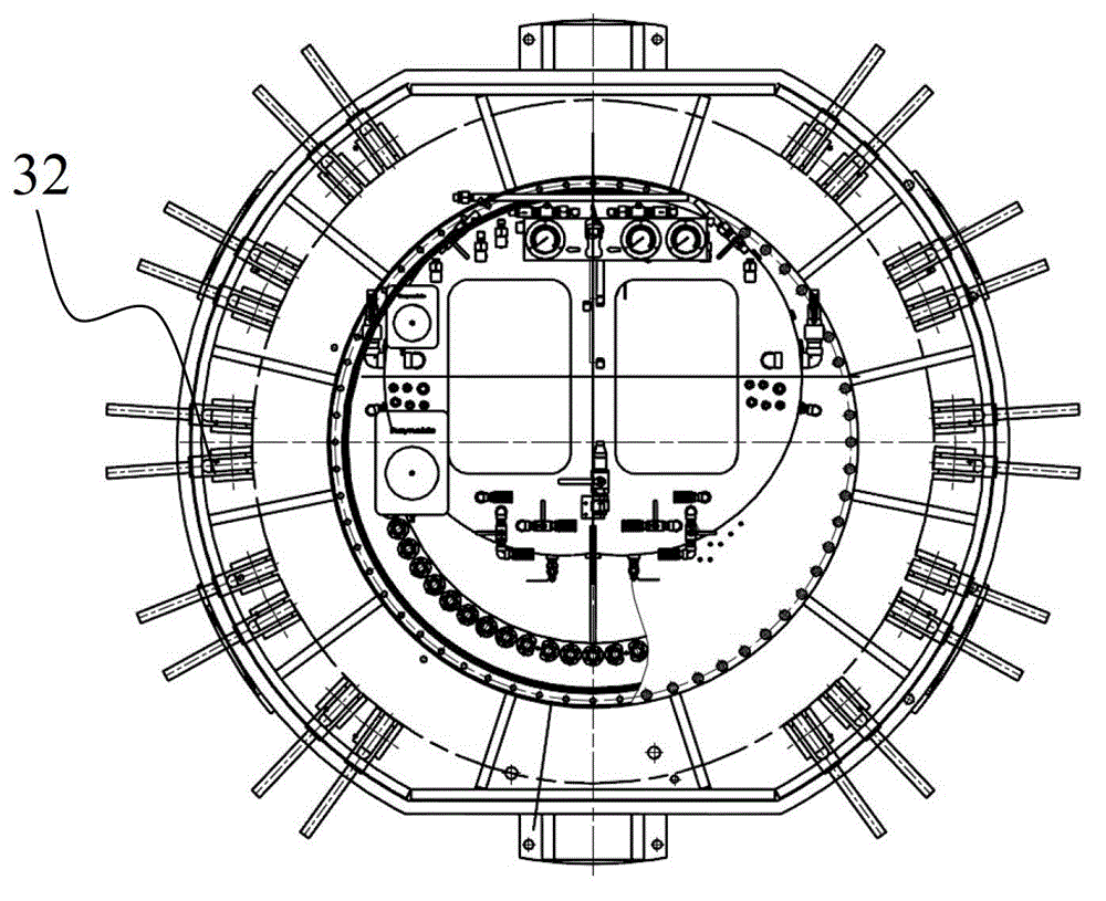
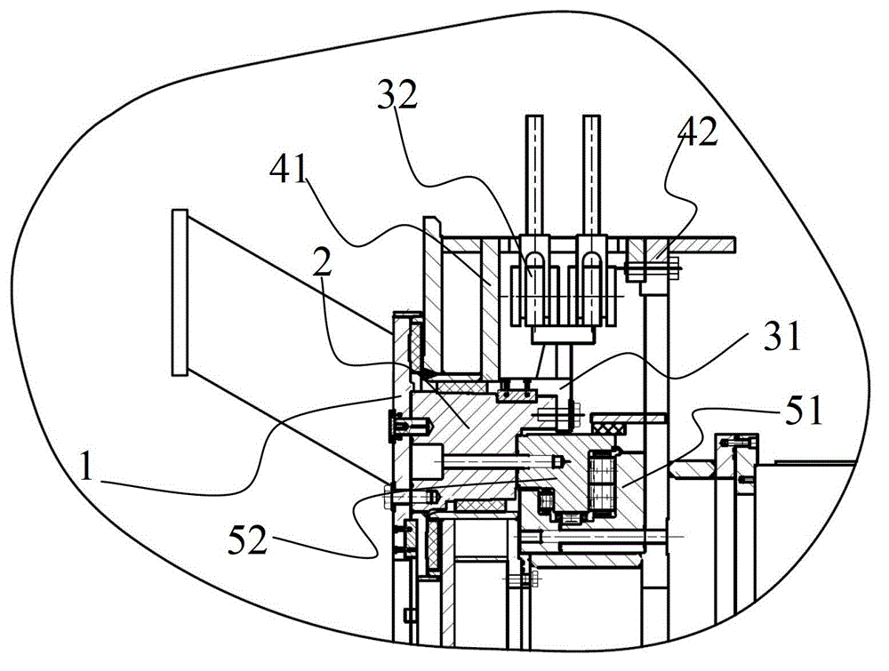
[0019] Please refer to Figure 1-Figure 5 , the cam ring motor-driven shield cutter head driving device of the present invention includes a power box 4, the power box 4 is the support and installation box structure of the entire cutter head drive device, and is fixed to the shell of the shield machine 7 on. The power box 4 is provided with a transmission structure and a cam motor device 3, and the cam motor device 3 is connected to the cutter head of the shield machine through the transmission structure; the transmission structure includes a force transmission ring 1, a force ring 2 and a large bearing 5, The force ring 2 is connected to the cam motor device 3 by transmission; the force ring 2 is connected to the force transmission ring 1 by bolts; the cam ring motor device 3 provides the power of the cutter head drive device, including a cam ...


PUM


Abstract

The invention discloses a shield cutter head driving device with a cam ring motor applied. The driving device comprises a power box, wherein a transmission structure and a cam motor device are arranged in the power box, the cam motor device is connected with a shield cutter head in a transmission mode through the transmission structure, the power box is fixedly connected with a shield shell body, multiple rows of hydraulic oil cylinders are arranged on the cam ring motor device in the radial direction, a plurality of hydraulic oil cylinders are distributed in each row in the circumferential direction, a cam ring is driven to rotate through reciprocating motions of the hydraulic oil cylinders, and therefore the shield cutter head is driven to rotate through the transmission structure. The shield cutter head driving device with the cam ring motor has the advantages of being simple in manufacturing technology, simple in transmission structure and capable of greatly reducing the cost of the driving device of a domestic shield machine cutter head.

Description

technical field [0001] The invention relates to a driving device for a shield machine cutter head, in particular to a shield machine cutter head driving device using a cam ring motor driving method. Background technique [0002] The cutter head drive device of the shield machine is a device that drives the cutter head to rotate, and is mainly composed of the cutter head drive power device, main bearing, soil and sand seal, etc. Usually there are two forms of hydraulic drive and motor drive. These two types of cutter head drive devices have basically similar structural types, but the transmission type is relatively complicated, and the processing and manufacturing process requires high precision and high cost. Moreover, because my country's domestic manufacturing industry is relatively backward compared with developed countries in Europe and the United States, the degree of localization of main bearings, oil motors, and reducers is not high, and they often need to be importe...

Claims


Application Information

Patent Timeline
Patent Type & Authority Applications(China)
IPC IPC(8): E21D9/08
Inventor 闵锐顾建江顾旭莹
Owner SHANGHAI TUNNEL ENG CO LTD
Learn More