Device and method for controlling electronic-controlled engine

An electronically controlled engine and engine technology, applied in the direction of engine control, machine/engine, program control, etc., can solve the problem of not being able to test the electronically controlled engine, and achieve the effect of saving time

Active Publication Date: 2013-10-02
DONGFENG CUMMINS ENGINE
View PDF6 Cites 14 Cited by
  • Summary
  • Abstract
  • Description
  • Claims
  • Application Information

AI Technical Summary

Problems solved by technology

Ordinary engine benches cannot send J1939 message commands to the ECM,

Method used


Image

  • Device and method for controlling electronic-controlled engine
  • Device and method for controlling electronic-controlled engine
  • Device and method for controlling electronic-controlled engine

Examples


Embodiment Construction

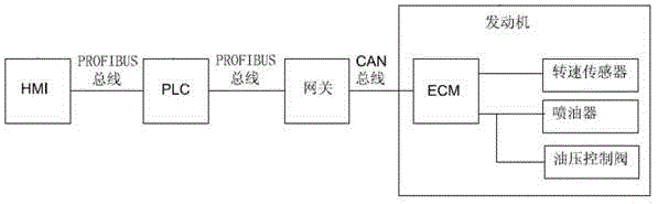
[0049] figure 1 It is a block diagram of the HMI principle of the industrial computer of the present invention: a device for controlling an electronically controlled engine of the present invention includes an industrial computer with a touch screen, a programmable logic controller PLC, a gateway, an electronic control module ECM of an electronically controlled engine, a speed sensor, and a fuel injection The industrial computer is connected to the PLC through the ProfiBus bus, the PLC is connected to the gateway through the ProfiBus bus, the gateway is connected to the electronic control module ECM through CAN, and the electronic control module ECM is connected to the engine sensor, fuel injector and connected to the oil pressure control valve.

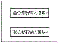
[0050] figure 2 It is a functional block diagram of the industrial computer HMI of the present invention.

[0051] The industrial computer HMI includes a command parameter input module and a status parameter output module. Comman...


PUM


Abstract

The invention discloses a device and method for controlling an electronic-controlled engine. The device comprises an IPC (Industrial Personal Computer) with a touch screen, a PLC (Programmable Logic Controller), a gateway, an ECM (electronic control module) of an electronic-controlled engine, a rotating speed sensor, an oil atomizer and an oil pressure control valve, wherein the gateway integrates a ProfiBus system and a CAN bus system into a whole, so as to enable the IPC attached to the ProfiBus system to send command values of rotating speed, torque and accelerator opening degree to the ECM attached to the CAN bus system, and then the ECM controls an engine to operate; meanwhile, the ECM can send the actual values of the rotating speed, the torque and the accelerator opening degree of the engine to the IPC, so as to realize the monitoring and control for the electronic-controlled engine; the PLC places parameters read from the IPC into an output cache module inside the PLC; the ProfiBus-J1939 gateway reads parameters from the output cache module of the PLC and sends the parameters to the ECM of the engine through the CAN bus; the ECM obtains the engine command value parameters to control the operation of the engine.

Description

technical field [0001] The invention relates to a device and method for controlling an electronically controlled engine, in particular to programmable logic controller (PLC) technology, electronically controlled engine control technology and field bus technology, belonging to the technical field of electronically controlled engine and electrical control technology, applicable to The electronically controlled engine is a construction machinery and test equipment with adjustable power and working conditions. Background technique [0002] Some non-vehicle engines do not directly use the accelerator pedal to control the speed and torque of the engine, but directly send the speed, torque or accelerator opening to the electronic control module ECM of the electronically controlled engine through the J1939 message to control the operation of the engine. Before leaving the factory, the engine must pass the test on the engine bench before it can be sent to the customer. A common engi...

Claims


Application Information

Patent Timeline
IPC IPC(8): F02D28/00
Inventor 孙卫军柯采黄锐
Owner DONGFENG CUMMINS ENGINE
Why Eureka
Try Eureka