
Resonator optical gyroscope based on resonant intracavity modulation

A resonant cavity, optical gyroscope technology, applied in the field of photoelectric sensing, can solve the problems of non-modularity, high cost and large error of resonant optical gyroscope, and achieve the effect of simplifying the gyroscope model, enhancing the resonance characteristics and reducing the modulation voltage.

Active Publication Date: 2013-10-02
BEIHANG UNIV
View PDF5 Cites 14 Cited by
  • Summary
  • Abstract
  • Description
  • Claims
  • Application Information

AI Technical Summary

Problems solved by technology

[0004] The purpose of the present invention is to propose a resonant optical gyroscope based on modulation in a resonant cavity in order to solve the problems of non-modularization, difficulty in integration, large error and high cost in the resonant optical gyroscope

Method used


Image

  • Resonator optical gyroscope based on resonant intracavity modulation
  • Resonator optical gyroscope based on resonant intracavity modulation
  • Resonator optical gyroscope based on resonant intracavity modulation

Examples


Embodiment Construction

[0021] The present invention will be further described in detail with reference to the accompanying drawings and embodiments.

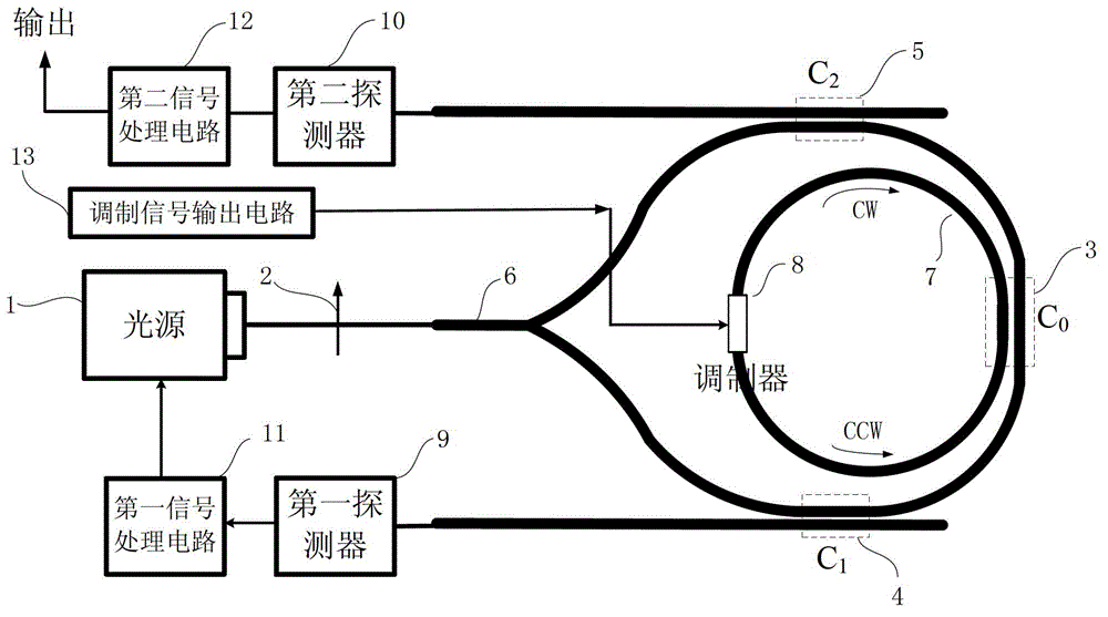
[0022] The present invention is a resonant optical gyroscope based on modulation in a resonant cavity, such as figure 2 As shown, a part of the resonant cavity is used as the modulator, and the modulator outside the cavity is replaced, including the light source 1, the isolator 2, and the coupler C 0 3. Coupler C 1 4. Coupler C 2 5. Passive Y-branch coupler 6 , resonant cavity 7 , modulator 8 , first detector 9 , second detector 10 , first signal processing circuit 11 , second signal processing circuit 12 , modulation signal output circuit 13 .

[0023] The light source 1 sends out an optical signal, the optical signal enters the isolator 2, the optical signal is transmitted unidirectionally through the isolator 2, the isolator 2 prevents the returned optical signal from reaching the light source 1, and the isolator 2 is connected to the input term...


PUM


Abstract

The invention discloses a resonator optical gyroscope based on resonant intracavity modulation. The resonator optical gyroscope comprises a light source, an isolator, a coupler C0, a coupler C1, a coupler C2, an inactive Y-branch coupler, a resonant cavity, a modulator, a first prober, a second prober, a first signal processing circuit, a second signal processing circuit and a modulation signal output circuit. The gyroscope provided by the invention uses the resonant intracavity modulation to replace an external two-circuit modulator structure, so that a gyroscope model is simplified and the integration degree of the gyroscope is greatly improved. The resonance characteristic of the resonant cavity provided by the invention enhances the modulation characteristic, so that a modulation voltage is reduced. Furthermore, the gyroscope provided by the invention is only provided with a modulation arm, however, a double modulation effect is achieved and the power consumption of the system is reduced. The modulation manner corresponding to the intracavity modulation provided by the invention uses a simple periodic square wave modulation curve, so that the non-linear error of the triangular wave is removed when being compared with the triangular wave modulation curve which is commonly used in external modulation; the asymmetry of a waveform is avoided; the gyroscope is beneficial to improvement on the entire precision of the gyroscope.

Description

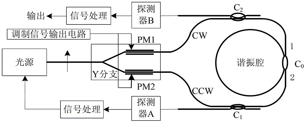
technical field [0001] The invention relates to a resonant optical gyroscope based on modulation in a resonant cavity, and belongs to the technical field of photoelectric sensing such as optical gyroscopes. Background technique [0002] At present, for optical sensors, how to reduce the structural size of devices, reduce device manufacturing costs, and improve the integration of optical sensors are high-tech pursuits in the world, especially in developed countries, governments, scientific and technological circles, and industries. [0003] At present, resonant optical gyroscopes mostly use figure 1 As shown in the system structure diagram, the light emitted by the light source is divided into two identical beams through the Y branch. The modulation signal output circuit outputs the modulation signal to the modulator PM1 and the modulator PM2, wherein the light in the clockwise direction (CW) passes through the modulator PM1 to adjust the transmission light frequency offset ...

Claims


Application Information

Patent Timeline
IPC IPC(8): G01C19/66
Inventor 冯丽爽王坤博王俊杰郅银周
Owner BEIHANG UNIV
Learn More