Bolt tightening force coefficient measuring method

A measurement method and technology of tightening force, applied in the direction of measuring devices, testing of mechanical components, testing of machine/structural components, etc., can solve the problems of large dispersion of K value, many factors affecting K value, and difficult to handle properly. To achieve the effect of preventing bolt overload and ensuring tightness

Active Publication Date: 2013-10-02
STATE GRID CORP OF CHINA +2
View PDF5 Cites 22 Cited by
  • Summary
  • Abstract
  • Description
  • Claims
  • Application Information

AI Technical Summary

Problems solved by technology

The data of K is very important in the design calculation and construction technology of connecting bolts. Germany, the United States, and Japan pay more attention to the research in this area, but they also feel that it is difficult to handle it properly because of the large dispersion of K values ​​in the actual measurement.
For example,

Method used


Image

  • Bolt tightening force coefficient measuring method
  • Bolt tightening force coefficient measuring method
  • Bolt tightening force coefficient measuring method

Examples


Embodiment 1

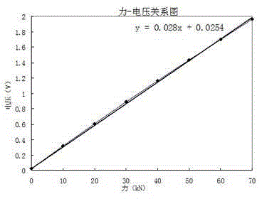
[0059] Step 1: Calibrate the pressure sensor, apply a force P of 0~180KN to the pressure sensor through the tensile test machine pressure fixture 0 , and record the voltage U of the force sensor 7 under different forces through the software of the tensile testing machine, the data of the force and voltage obtained are shown in Table 1, and the force-voltage curve is drawn as attached image 3As shown, according to the formula (1), the pressure-voltage relationship is obtained.

[0060] U=kF+b (1)

[0061] U——the voltage displayed by the pressure sensor, in V;

[0062] F——the force exerted by the tensile testing machine, in N;

[0063] k—coefficient, unit V / N;

[0064] b——the initial voltage displayed by the pressure sensor when the force is 0, in V.

[0065] The pressure-voltage relationship in this embodiment is: U=0.028 P0+0.0254.

[0066] Table 1 Pressure and sensor voltage detected during calibration of tensile testing machine

[0067]

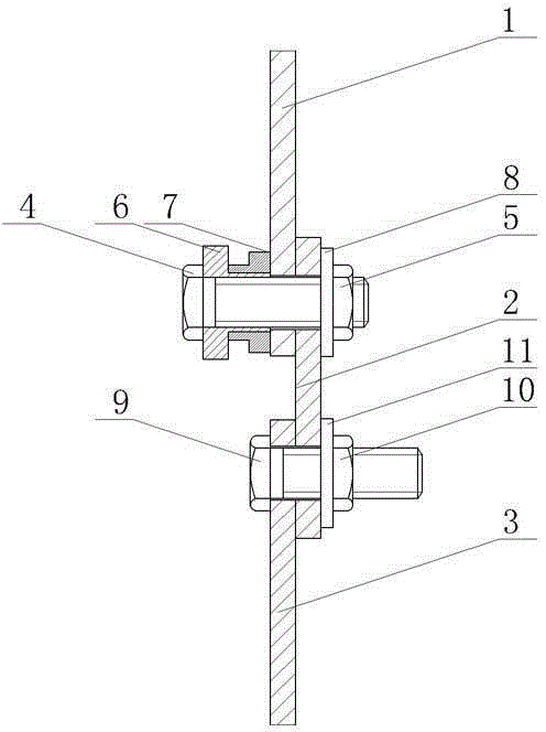
[0068] Step 2: As attached...


PUM

PropertyMeasurementUnit
Widthaaaaaaaaaa
Thicknessaaaaaaaaaa
Diameteraaaaaaaaaa

Abstract

The invention relates to a bolt tightening force coefficient measuring method, and especially is suitable for tightening force coefficient measuring of an iron tower galvanizing bolt. The method comprises the following steps: demarcating a pressure transducer, connecting an iron tower bolt tightening force coefficient simulation testing device, installing the simulation testing device in a tensile testing machine, acquiring pre-tightening force data, and calculating a tightening force coefficient. The method can be realized in a laboratory; the operation is easy; the test result is accurate; and the guiding significance is provided to the iron tower integral structure and stability assessment.

Description


Claims


Application Information

Patent Timeline
Owner STATE GRID CORP OF CHINA
Why Eureka
Try Eureka