In-situ testing device for micro-mechanical properties of materials under tension-shear combined loading mode

A micromechanics, in-situ testing technology, applied in the direction of testing the ductility of materials, etc., can solve the lack of in-depth research on macro-scale and cross-scale in-situ micro/nano mechanical performance testing, and the inability to carry out in-depth combination of composite loads and materials. In order to achieve good development and application prospects, rich test content, and enrich the effect of in-situ micro-nano mechanical properties testing

Active Publication Date: 2013-10-02
JILIN UNIV
View PDF5 Cites 30 Cited by
  • Summary
  • Abstract
  • Description
  • Claims
  • Application Information

AI Technical Summary

Problems solved by technology

This test method results in two or more load modes that cannot be loaded independently or sequentially, so it is difficult to analyze different single load modes, and it is also impossible to analyze the mechanical properties and properties of materials and their products under the combined load of different stress combinations. Accurate assessment of degenerative injury mechanisms
[0005] The current in-situ nanomechanical testing technology has the following limitations: (1) Most in-situ nano-testing focuses on the simple in-situ testing of extremely small structures such as nanotubes, nanowires, and thin-film materials based on the principle of micro/nano-electromechanical systems. In terms of nano-tensile testing, there is a lack of in-depth research on cross-scale in-situ micro/nano-mechanical performance testing of macroscopic dimensions (thin film materials or three-dimensional specimens); (2) the current in-situ mechanical testing mainly relies on commercial in-situ nano The tensile tester and the nano-indentation tester perform in-situ nano-tensile testing

Method used


Image

  • In-situ testing device for micro-mechanical properties of materials under tension-shear combined loading mode
  • In-situ testing device for micro-mechanical properties of materials under tension-shear combined loading mode
  • In-situ testing device for micro-mechanical properties of materials under tension-shear combined loading mode

Examples


Embodiment Construction

[0032] The detailed content of the present invention and its specific implementation will be further described below in conjunction with the accompanying drawings.

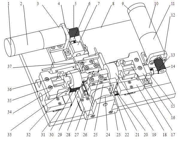
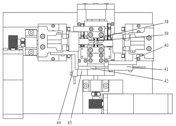
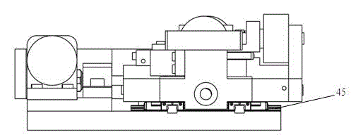
[0033] see Figure 1 to Figure 8 As shown, the in-situ test device for the micromechanical properties of materials under the tensile-shear composite loading mode of the present invention includes two parts: a tensile loading module and a shearing loading module, and the main structures of the tensile loading module and the shearing loading module are respectively It is composed of power components, transmission and execution components, signal detection and control components, and clamping support components;

[0034] The assembly relationship of the power components, transmission and execution components of the tensile loading module is: the hollow cup rotor DC motor I2 is connected with the planetary gear reducer I3, and then connected with the precision two-way ball screw I39 through the worm and worm gear pair...


PUM


Abstract

The invention relates to an in-situ testing device for micro-mechanical properties of materials under a tension-shear combined loading mode, and belongs to the in-situ test field of mechanical properties. A tension module and a shear module are composed of a motor power assembly, a transmission and execution assembly, a clamping support assembly, a signal detection and control assembly respectively. The shear module also comprises a piezoelectric driving assembly capable of applying high-frequency shear fatigue loading. A coreless rotor direct-current motor is connected with a planetary gear reducer and is connected with a precision bi-directional ball screw through a worm and gear transmission component; and square nuts connected with the ball screw nuts are supported and guided through guide rails at the two sides. Two loadings are respectively collect force and displacement signals by a precision force sensor and a linear motor power assembly potentiometer. The in-situ testing device is smart in size, compact in structure and high in test precision, can realize the tests of tension and shear loadings at different strain rates and stress ratios, and can be compatible with loading platforms of microscopic imaging equipment such as metallographic microscopes and the like.

Description

[0001] technical field [0002] The invention relates to the field of in-situ mechanical performance testing, in particular to an in-situ testing device for microscopic mechanical properties of materials under a tensile-shear composite loading mode. This device can be used independently as a test device for tensile and pure shear two kinds of material mechanical properties, and can also realize the composite load test of the two loads of tension and shear under different loading sequences, and can also perform high-frequency shear fatigue performance tests; The device can be placed under microscopic imaging equipment such as a metallographic microscope to observe in situ the microscopic morphology of the specimen during the tensile-shear composite load loading process, such as the generation, growth and expansion of microscopic cracks; it can realize load / Acquisition, conversion and control of displacement signals are used to accurately measure the mechanical properties of ma...

Claims


Application Information

Patent Timeline
IPC IPC(8): G01N3/28
Inventor 赵宏伟董晓龙胡晓利程虹丙高景邵明坤张攀峰
Owner JILIN UNIV
Why Eureka
Try Eureka