Low ripple current output circuit

An output circuit, low-ripple technology, applied in the field of low-ripple current output circuits, can solve the problems of not being able to meet load changes, the output filter inductance is large, and the dynamic characteristics are slow. Small inductor weight and improved dynamic characteristics

Active Publication Date: 2013-10-09
SHENZHEN AEROSPACE NEW POWER TECH
View PDF4 Cites 9 Cited by
  • Summary
  • Abstract
  • Description
  • Claims
  • Application Information

AI Technical Summary

Problems solved by technology

[0004] In the actual design process of low output current ripple, in order to meet the index requirements, the calculated output filter inductance L is very large. At this time, the overall dynamic characteristics will slow down due to the increase of L, so that it cannot meet the requirements. The requirement of load change brings many problems to the selection and production of magnetic materials, such as volume increase, cost increase, etc.

Method used


Image

  • Low ripple current output circuit
  • Low ripple current output circuit
  • Low ripple current output circuit

Examples


Embodiment Construction

[0025] The present invention will be further described below in conjunction with the accompanying drawings and specific embodiments.

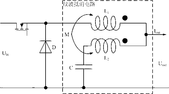
[0026] Such as figure 2 As shown, the low ripple current output circuit of the embodiment of the present invention includes a freewheeling diode and a ripple cancellation circuit connected between the positive pole and the negative pole of the freewheeling diode. The negative pole of the freewheeling diode is connected to the positive pole of the current source, and its positive pole is connected to the current source. Source negative pole, the output terminal of the ripple canceling circuit is used as the output of the low ripple current output circuit.

[0027] Such as figure 2 As shown, the ripple cancellation circuit includes an energy storage capacitor C and a coupled inductor L 1 and inductance L 2 , inductance L 1 with inductance L 2 opposite of the same-named end, the inductance L 1 One end of the freewheeling diode is connected...


PUM


Abstract

The invention provides a low ripple current output circuit which comprises a fly-wheel diode and a ripple compensating circuit connected between the positive pole of the diode and the negative pole of the diode, wherein the negative pole of the fly-wheel diode is connected with the positive pole of a current source, the positive pole of the fly-wheel diode is connected with the negative pole of the current source, and the output end of the ripper compensating circuit is used as the output end of the low ripple current output circuit. Due to the fact that the ripper compensating circuit is added to a traditional low ripple current output circuit, steady-state performance is guaranteed, and requirements for dynamic performance are met.

Description

technical field [0001] The invention relates to a low ripple current output circuit. Background technique [0002] Switching current sources with low output current ripple can be used in low-voltage and high-current distributed power systems such as new energy, computers, and automobiles, and can effectively reduce high-order harmonic components caused by current ripple. In order to meet the output current ripple requirements of the current source, the design of the filtering link is extremely important, and it has an important impact on the dynamic response and performance of the entire system. [0003] The design of the traditional step-down current mode switching power supply is as follows: figure 1 As shown, in order to reduce the output current ripple, a single-stage or multi-stage filter is usually used, or a two-phase interleaving method is used to achieve mutual cancellation of the output current. figure 1 in, U in is the input voltage, U out Is the output voltag...

Claims


Application Information

Patent Timeline
Patent Type & Authority Applications(China)
IPC IPC(8): H02M1/14
Inventor 张东来刘贺张迪施凯敏鲍志云
Owner SHENZHEN AEROSPACE NEW POWER TECH
Why Eureka
Try Eureka