A PLL Applicable to Grid Voltage Unbalance and Distortion State
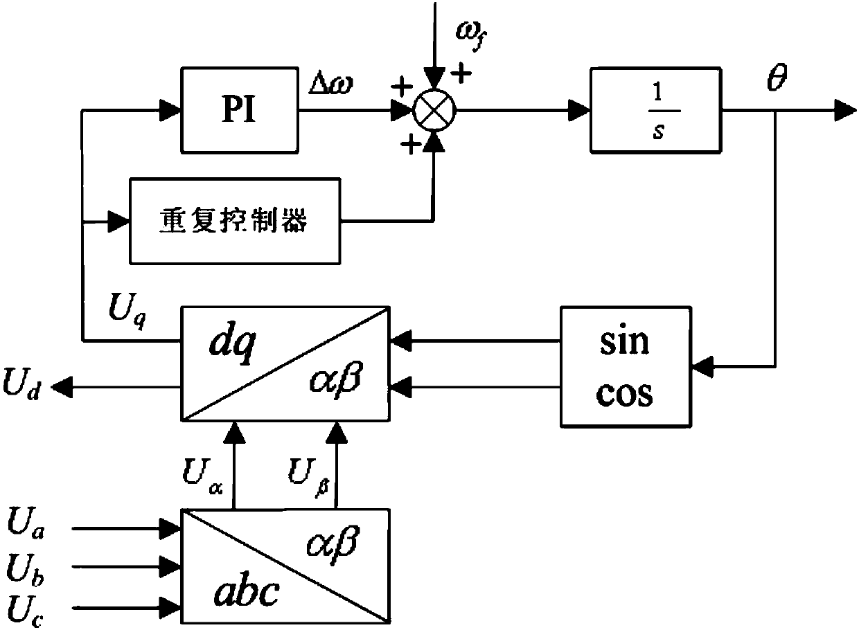
A grid voltage, phase-locked loop technology, applied in the field of phase-locked loops, can solve the problems of phase-locked results discrete error, etc., and achieve the effects of fast dynamic response rate, small phase detection error, and small steady-state error.
- Summary
- Abstract
- Description
- Claims
- Application Information
AI Technical Summary
Problems solved by technology
Method used
Image
Examples
Embodiment 1
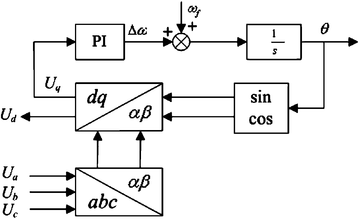
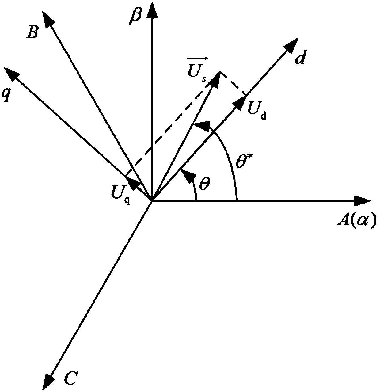
[0047] figure 1 It is the schematic diagram of the basic three-phase phase-locked loop. The three-phase grid voltage is transformed into the two-phase static coordinate system by using the Clark transformation, and the voltage U of the grid voltage in the two-phase static coordinate system is obtained. α and U β , and then use the Parker transformation to transform the voltage value of the grid voltage in the two-phase stationary coordinate system to the two-phase rotating coordinate system, and obtain the voltage U of the grid voltage in the two-phase rotating coordinate system d and U q , where the grid voltage component on the q-axis is:
[0048]
[0049] When the phase angle θ output by the PLL is close to the phase angle ωt of the actual grid voltage vector, that is to say (ωt-θ) is very small or close to zero, sin(ωt-θ) can be approximated as (ωt-θ) . Therefore, when the PLL is locked, the q-axis component of the grid voltage vector in the synchronous rotating coo...
PUM
 Abstract
Description
Claims
Application Information
 - R&D
- Intellectual Property
- Life Sciences
- Materials
- Tech Scout
- Unparalleled Data Quality
- Higher Quality Content
- 60% Fewer Hallucinations
Browse by: Latest US Patents, China's latest patents, Technical Efficacy Thesaurus, Application Domain, Technology Topic, Popular Technical Reports.
© 2025 PatSnap. All rights reserved.Legal|Privacy policy|Modern Slavery Act Transparency Statement|Sitemap|About US| Contact US: help@patsnap.com


