Gradient-reference-current control system and method of pseudo continuous conduction mode Buck converter

A pseudo-continuous conduction, reference current technology, applied in the control/regulation system, converting DC power input to DC power output, adjusting electrical variables, etc., can solve the problem of reducing the duty cycle of the inductor freewheeling stage and increasing the inductor freewheeling It can solve the problems such as stage duty cycle and converter efficiency reduction, so as to ensure the steady-state performance, improve the dynamic response speed, and ensure the dynamic response speed.

Inactive Publication Date: 2016-12-14
WUHAN UNIV
View PDF4 Cites 3 Cited by
  • Summary
  • Abstract
  • Description
  • Claims
  • Application Information

AI Technical Summary

Problems solved by technology

However, when the load is heavier, the increase of the average value of the inductor current will reduce the duty cycle of the inductor during the freewheeling phase, or even reduce the duty cycle of the freewheeling phase to zero, which will affect the improvement of the dynamic performance; when the load is lightened, the average value of the inductor current The reduction of the inductor will increase the duty cycle of the freewheeling phase, thereby reducing the efficiency of the converter

Method used


Image

  • Gradient-reference-current control system and method of pseudo continuous conduction mode Buck converter
  • Gradient-reference-current control system and method of pseudo continuous conduction mode Buck converter
  • Gradient-reference-current control system and method of pseudo continuous conduction mode Buck converter

Examples


Embodiment Construction

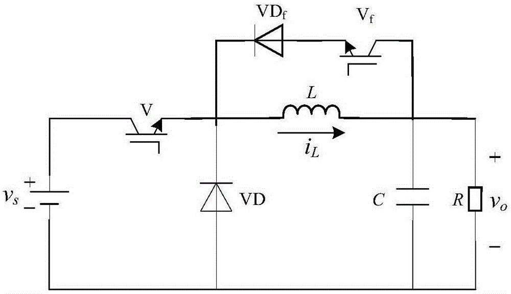
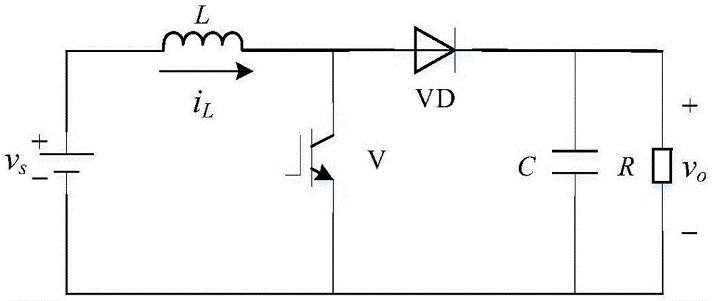
[0042] The present invention will be further elaborated below in conjunction with the accompanying drawings and specific implementation. In the figure,

[0043]L, C, R - inductance, capacitance, resistance, v s ——Input voltage, v o ——Output voltage, V——Main switch tube and its control signal, V f ——Freewheel switch tube and its control signal, VD——Diode, VD f - freewheeling diode, i L ——inductor current, V ref ——voltage command value, D f ——Duty ratio of inductor freewheeling phase, t onmin ——Minimum blocking time, I dcn , I dc(n-1) ,..., I dc0 —— gradient reference current value, pulse —— clock signal, t s - adjustment time, t - simulation time.

[0044] 1. First, introduce the system and method of the present invention.

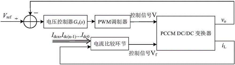
[0045] 1. Gradient reference current control system (system for short)

[0046] The system includes two parts, the voltage loop and the current loop, and its control block diagram is as follows: image 3 shown.

[0047] The voltage loop is co...


PUM


Abstract

The invention relates to a gradient-reference-current control system and method of a pseudo continuous conduction mode Buck converter. The gradient-reference-current control system comprises two parts, i.e., a voltage loop and a current loop; the voltage loop comprises a voltage controller and a PWM modulator, and is used for controlling a main switch tube of the pseudo continuous conduction mode Buck converter; the current loop is mainly composed of inductive current and a gradient reference current comparison element, and is used for controlling a follow current switch tube of the pseudo continuous conduction mode Buck converter. In the premises of not needing to sample load current and reducing a hardware structure, the gradient-reference-current control system can quicken the dynamic response speed of the pseudo continuous conduction mode Buck converter in a wide load change range.

Description

technical field [0001] The invention belongs to the field of power electronics, and relates to a control method for a pseudo continuous conduction mode (Pseudo Continuous Conduction Mode, PCCM) Buck converter, in particular to a method for improving the dynamic response of a PCCM Buck converter. Background technique [0002] Switching converters are widely used in portable electronic devices due to their low quiescent current, high efficiency and small size. With the development of integrated circuits, the requirements for the dynamic performance of the power supply are getting higher and higher for the widely used portable equipment. [0003] PCCM was first proposed in the Boost converter, adding a freewheeling switch tube and a freewheeling diode to the topology of the traditional Boost converter, thereby adding a control degree of freedom to eliminate the control to the right half of the output transfer function of the traditional Boost converter The zero point of the pl...

Claims


Application Information

Patent Timeline
Patent Type & Authority Applications(China)
IPC IPC(8): H02M3/156
CPCH02M3/156H02M3/1566
Inventor 廖书寒刘飞查晓明冯锟胡伟周辉
Owner WUHAN UNIV
Why Eureka
Try Eureka