Mechanical synchronous hybrid relay and hybrid switch operating method

A hybrid relay and mechanical synchronization technology, applied in relays, electronic switches, circuits, etc., can solve the problems of limited synchronization effect, unsolved semiconductor switch off synchronization, input voltage fluctuations, etc., to achieve a wide range of working voltage and eliminate soft features The effect of failure, shortening the transition process

Active Publication Date: 2015-11-18
G & A TECH
View PDF5 Cites 0 Cited by
  • Summary
  • Abstract
  • Description
  • Claims
  • Application Information

AI Technical Summary

Problems solved by technology

[0002] Existing hybrid relays (see Figure 4 ) can be regarded as a simple combination of two unrelated independent systems of an electromechanical relay and a solid state relay. Synchronous on-off switching (see Figure 5 )
When the input voltage fluctuates greatly, the asynchronous phenomenon will be aggravated; this simple combination of hybrid relays, in high-power applications with a load surge current of hundreds of amperes, is likely to cause damage to the semiconductor switch that is first turned on, especially in When the semiconductor switch has soft characteristics, the semiconductor switch and the mechanical contact switch will eventually fail due to high voltage and high current; what is more serious is that the electromechanical relay inside the hybrid relay does not operate for some reason, which will cause the semiconductor switch that is turned on alone to be damaged due to overcurrent. Power supply accident caused by burning
[0003] The hybrid relay solution disclosed in the Chinese invention patent "Low Power Consumption Hybrid Relay and Its Operation Method" with the notification number CN101465636A uses a threshold circuit to solve input voltage fluctuations, and uses a delay circuit to hysteresis control the conduction of the semiconductor switch, only making the semiconductor switch conduction Synchronized with mechanical contact switches (see Image 6 ), but did not solve the problem of the synchronization of the semiconductor switch off; due to the discreteness of the action time of the electromechanical relay, the synchronization effect is very limited, and it also complicates the manufacturing; when the internal electromechanical relay does not operate for some reason, the semiconductor Switches will still cause power supply accidents due to overcurrent burnout

Method used


Image

  • Mechanical synchronous hybrid relay and hybrid switch operating method
  • Mechanical synchronous hybrid relay and hybrid switch operating method
  • Mechanical synchronous hybrid relay and hybrid switch operating method

Examples


Embodiment 1

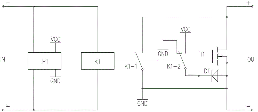
[0029] This embodiment is a DC type mechanical synchronous hybrid relay, the schematic diagram of the DC type mechanical synchronous hybrid relay is as follows figure 2As shown, the working timing diagram of the mechanical synchronous hybrid relay is as follows Figure 7 shown.

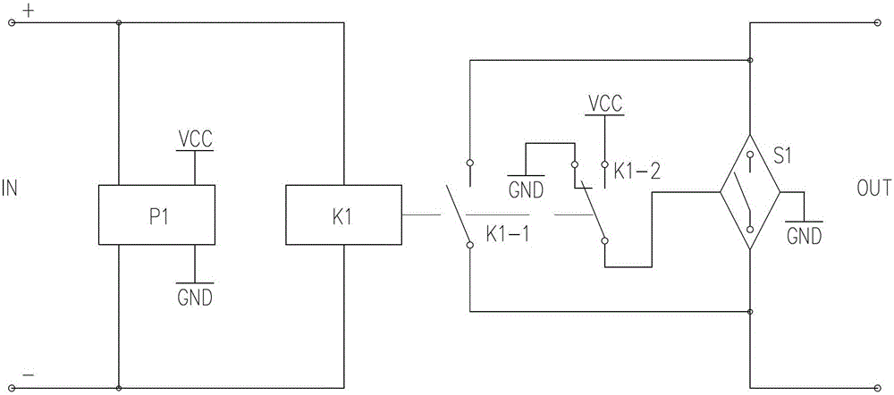
[0030] A DC type mechanical synchronous hybrid relay is mainly composed of an electromechanical relay and a solid state relay. The above-mentioned electromechanical relay includes a relay coil K1 and a mechanical contact switch. The above-mentioned solid state relay includes a driving power source P1 and a semiconductor switch S1. Wherein, the semiconductor switch S1 includes a field effect transistor T1, and a Zener diode D1 connected in parallel with the gate and source of the field effect transistor T1. The input terminal of the driving power P1 and the relay coil K1 are connected to the input terminal of the hybrid relay, and the driving power P1 provides energy support for the conduction of t...

Embodiment 2

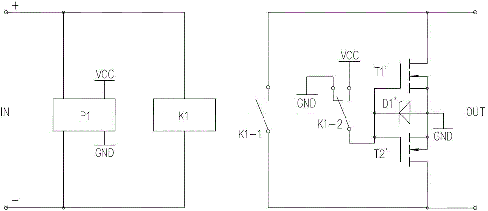
[0036] This embodiment is an AC-DC type mechanical synchronous hybrid relay, and the schematic diagram of the DC type mechanical synchronous hybrid relay is as follows image 3 As shown, the working timing diagram of the mechanical synchronous hybrid relay is as follows Figure 7 shown.

[0037] Embodiment 2 is based on Embodiment 1, and a reverse conduction semiconductor switch field effect transistor T2' is added on the basis of the field effect transistor T1' of the forward conduction semiconductor switch S1, so that S1 becomes a bidirectional semiconductor switch. Controls the switching on or off of AC or DC current. The source of the field effect transistor T1', the source of the field effect transistor T2' and the cathode of the Zener diode D1' are connected. The gate of the field effect transistor T1', the gate of the field effect transistor T2' are connected to the anode of the Zener diode D1'.

[0038] The control mode of embodiment 2 is the same as that of embodim...


PUM


Abstract

The invention discloses a method for mechanically and synchronously operating a hybrid relay and a hybrid switch. The method comprises the following steps that a single-pole double-throw synchronous mechanical contact switch is arranged in an electromechanical relay of the hybrid relay, wherein the single-pole double-throw synchronous mechanical contact switch connects the input control terminal of a semiconductor switch with a driving power supply or with the ground and controls the semiconductor switch to be switched on or switched off. When a control voltage is applied on the input terminal of the hybrid relay, a voltage is applied on the driving power supply at the same time so that the driving power supply starts to work, by utilizing the characteristic that the switch-on a mechanical contact switch of the electromechanical relay lags behind the start of the driving power supply, the effect that the driving power supply establishes hard characteristics when the synchronous mechanical contact switch connects the control terminal of the semiconductor switch with the driving power supply is guaranteed, and adequate energy support can be provided when the semiconductor switch is switched on. The method for mechanically and synchronously operating the hybrid relay and the hybrid switch can realize synchronous breakover or turn-off of the semiconductor switch and the synchronous mechanical contact switch, and solves the problem that soft characteristics of the semiconductor switch lose efficacy.

Description

technical field [0001] The invention relates to the field of hybrid relays, in particular to a mechanical synchronous hybrid relay and a hybrid switch operation method. Background technique [0002] Existing hybrid relays (see Figure 4 ) can be regarded as a simple combination of two unrelated independent systems of an electromechanical relay and a solid state relay. Synchronous on-off switching (see Figure 5 ). When the input voltage fluctuates greatly, the asynchronous phenomenon will be aggravated; this simple combination of hybrid relays, in high-power applications with a load surge current of hundreds of amperes, is likely to cause damage to the semiconductor switch that is first turned on, especially in When the semiconductor switch has soft characteristics, the semiconductor switch and the mechanical contact switch will eventually fail due to high voltage and high current; what is more serious is that the electromechanical relay inside the hybrid relay does not op...

Claims


Application Information

Patent Timeline
Patent Type & Authority Patents(China)
IPC IPC(8): H03K17/08H01H47/02
Inventor 彭世益
Owner G & A TECH
Why Eureka
Try Eureka