

Numerical control gantry vertical and horizontal combined machining center of combination of tool magazine and main shaft on saddle
A compound machining center and saddle technology, applied in metal processing equipment, metal processing machinery parts, manufacturing tools, etc., can solve problems such as inability to change tools in time, low work efficiency, and inability to perform left and right feed movements, etc., to achieve heavy weight Load cutting and energy-saving machining, and the effect of improving machining efficiency
- Summary
- Abstract
- Description
- Claims
- Application Information
AI Technical Summary
Problems solved by technology
Method used
Image

Examples
Embodiment 1
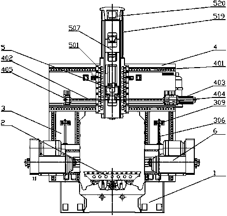
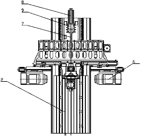
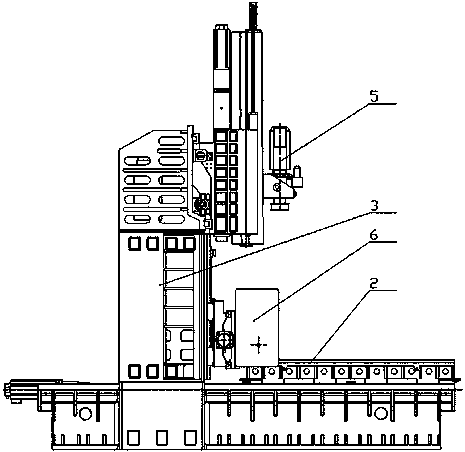
[0053] Embodiment 1: In this example, a CNC gantry vertical and horizontal composite machining center in which the tool magazine and the spindle are combined on the saddle, such as figure 1 , figure 2 , image 3 , There is a base 1, the base is movably connected with a workbench 2 through a guide rail, the workbench is movably connected with a workbench screw 7, the workbench screw is connected with a servo motor 8, and the servo motor is fixed on the base through a servo motor base 9 . The base is also provided with two uprights 3, the uprights are fixedly connected with a crossbeam 4, the upper part of the crossbeam is fixed with a top beam, the crossbeam is provided with a crossbeam guide rail 401, and the crossbeam guide rail is movably connected with one or more vertical spindle devices 5 , the column is connected with one or more laterally movable horizontal spindle devices 6 through the column saddle screw rod 306, and the vertical spindle device and the horizontal s...
Embodiment 2
[0059] Embodiment 2: In this example, a CNC gantry vertical-horizontal compound machining center in which the tool magazine and the main shaft are combined on the saddle, such as figure 1 , figure 2 , image 3 , There is a base 1, the base is movably connected with a workbench 2 through a guide rail, the workbench is movably connected with a workbench screw 7, the workbench screw is connected with a servo motor 8, and the servo motor is fixed on the base through a servo motor base 9 . The base is also provided with two uprights 3, the uprights are fixedly connected with a crossbeam 4, the upper part of the crossbeam is fixed with a top beam, the crossbeam is provided with a crossbeam guide rail 401, and the crossbeam guide rail is movably connected with one or more vertical spindle devices 5 , the column is connected with one or more laterally movable horizontal spindle devices 6 through the column saddle screw rod 306, and the vertical spindle device and the horizontal spi...
Embodiment 3
[0065] Embodiment 3: A CNC gantry vertical-horizontal composite machining center in which the tool magazine and the main shaft are combined on the saddle in this example, such as figure 1 , figure 2 , image 3 , There is a base 1, the base is movably connected with a workbench 2 through a guide rail, the workbench is movably connected with a workbench screw 7, the workbench screw is connected with a servo motor 8, and the servo motor is fixed on the base through a servo motor base 9 . The base is also provided with two uprights 3, the uprights are fixedly connected with a crossbeam 4, the upper part of the crossbeam is fixed with a top beam, the crossbeam is provided with a crossbeam guide rail 401, and a vertical spindle device 5 is movably connected on the crossbeam guide rail, and the upright column passes through the upright The saddle screw rod 306 is connected with two horizontally movable horizontal spindle devices 6, the two horizontal spindle devices are arranged o...
PUM
 Abstract
Description
Claims
Application Information