Material cutting machine

A material cutting machine and material technology, applied in the direction of casting molding equipment, metal processing, etc., can solve problems such as wasting time, achieve the effect of improving precision, improving cast iron quality, and improving work efficiency

Inactive Publication Date: 2013-10-16
兴化市天和机械配件厂
View PDF6 Cites 19 Cited by
  • Summary
  • Abstract
  • Description
  • Claims
  • Application Information

AI Technical Summary

Problems solved by technology

In order to tighten the shreds, there is often a heavy lead pendant hanging from the lower end of the shreds. I

Method used


Image

  • Material cutting machine
  • Material cutting machine

Examples


Embodiment 1

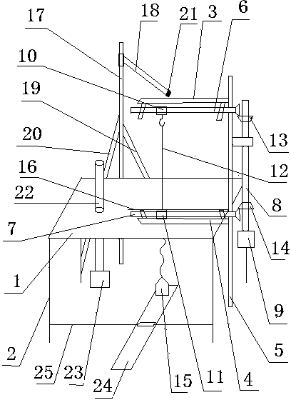
[0022] see figure 1 , the material cutting machine, including:

[0023] Operating platform assembly: including operating platform 1 and operating platform feet 2, the operating platform feet 2 are fixed on the operating platform 1, and the operating platform feet include two front operating platform feet and two rear operating platform feet;

[0024] Bracket assembly: including the bracket upper cross arm 3, the bracket lower cross arm 4 and the bracket rod 5, the bracket upper cross arm 3 and the bracket lower cross arm 4 are all vertically fixed on the bracket rod 5, the bracket upper cross arm 3 is located above the operating table 1, and the lower cross arm 4 of the bracket is located below the operating table 1;

[0025] Cutting assembly: including upper screw mandrel 6, lower screw mandrel 7, transmission shaft 8, first motor 9, upper slider 10, lower slider 11, shredded wire 12, said upper screw mandrel 6 and lower screw mandrel 7 pass through the umbrella Shaped gear...


PUM


Abstract

The invention provides a material cutting machine. The material cutting machine comprises an operation table assembly, a support assembly, a supporting assembly, a rotating assembly and a cutting assembly, and further comprises a rectangular pedal, wherein a table leg transverse rod is arranged between two front operation table legs, the pedal is installed on the table leg transverse rod and can rotate with the table leg transverse rod as the axis, the front end of the pedal is located below a lead weight, and when the front end of the pedal is located at the highest point, the lead weight is supported by the pedal, and a cutting line is in a loosing state. A rotating shaft is adopted to drive materials to rotate, and regular circles can be cut out; the supporting assembly enables a support not to move easily when the machining is conducted; an upper screw rod and a lower screw rod rotate at the same time through a transmission shaft to regulate the position of the upper end and the lower end of the cutting line at the same time, and working efficiency is improved. The lower end of the cutting line is connected with the lead weight to tension the cutting line, and the appearance of a die which is cut out is much smoother. The pedal is further arranged, so that the cutting line is convenient to take down from or hang on an upper slide block, and the material cutting machine is convenient and rapid to use.

Description

technical field [0001] The invention relates to a material cutting machine, which belongs to the lost foam casting industry. Background technique [0002] Lost foam casting (also known as solid casting) is to bond and combine paraffin or foam plastic models similar in size and shape to the castings to form a model cluster. Press down and pour to vaporize the model, liquid metal occupies the position of the model, solidifies and cools to form a new casting method. Lost Foam Casting is a new technology with nearly no allowance and precise molding. This technology does not need to take molds, has no parting surface, and no sand core, so the casting has no flash, burr, and draft angle, and reduces the risk of damage caused by the core. Dimensional errors caused by combination. The surface roughness of the casting can reach Ra3.2 to 12.5μm; the dimensional accuracy of the casting can reach IT7 to 9; the machining allowance is at most 1.5 to 2mm, which can greatly reduce the cos...

Claims


Application Information

Patent Timeline
IPC IPC(8): B26D1/547B26D7/08B26D7/26B22C7/02
Inventor 金迎年
Owner 兴化市天和机械配件厂
Why Eureka
Try Eureka