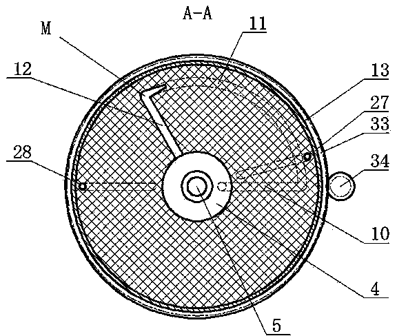
Rotary vacuum degassing device
A technology of vacuum degassing device and driving device, which is applied in the field of vacuum refining equipment for molten metal, to achieve the effects of expanding market application range, reducing supporting costs, and simplifying complexity
Inactive Publication Date: 2013-10-16
党浩然
View PDF4 Cites 6 Cited by
- Summary
- Abstract
- Description
- Claims
- Application Information
AI Technical Summary
Problems solved by technology
The purpose of the present invention is to provide a rotary vacuum degassing device, which can solve the shortcomings of the existing vacuum refining equipment outside the furnace
Method used
View moreImage
Smart ImageViewing Examples
Examples
Embodiment Construction
Login to View More PUM
 Abstract
The invention provides a rotary vacuum degassing device which comprises a rotary machine body, wherein an axial line of the rotary machine body is inclined 15 degrees to 75 degrees relative to a horizontal plane; the rotary machine body is connected with a driving device and rotates around a shaft core of the rotary machine body under the drive of the driving device; the lower end of the rotary machine body is a lower column, the upper end of the rotary machine body is an upper column, and the middle part of the rotary machine body is a middle column; each column is formed by an integral metal shell in a surrounding way; the inner part of the rotary machine body is an integral refractory material lining formed by pouring; a molten metal discharging passage, a refining chamber and a negative pressure passage are respectively formed in the refractory material linings of the upper column, the middle column and the lower column on a shaft core line of the rotary machine body and are communicated mutually; the discharging passage at the lower end of the rotary machine body is communicated with a refining liquid area through a refining liquid conduit; the negative pressure passage at the upper end is communicated with a vacuum bleed-off passage. The rotary vacuum degassing device can overcome defects existing in conventional vacuum refining equipment outside a furnace.
Description
technical field The invention relates to a vacuum refining equipment for molten metal, in particular to a rotary vacuum degassing device. Background technique With the progress and development of society, people have higher and higher requirements for the performance of steel. This requires that the out-of-furnace refining production in the steelmaking process can provide clean and ultra-clean molten steel. Vacuum degassing refining is currently the most ideal means of degassing and refining. Among many vacuum refining equipment, RH vacuum cycle degassing device is widely recognized by people because of its large processing capacity, short refining cycle and good refining effect; it has become the most typical vacuum processing equipment recognized by everyone. And it has been applied to some large steel enterprises. However, the inherent weakness of the device itself limits its scope of application: ①The liquid to be treated and the molten metal are mixed directly, maki...
Claims
Login to View More Application Information
Patent Timeline
 IPC IPC(8): C21C7/10
Inventor 党祎贤党浩然
Owner 党浩然
Features
- R&D
- Intellectual Property
- Life Sciences
- Materials
- Tech Scout
- Unparalleled Data Quality
- Higher Quality Content
- 60% Fewer Hallucinations
Learn More Browse by: Latest US Patents, China's latest patents, Technical Efficacy Thesaurus, Application Domain, Technology Topic, Popular Technical Reports.
© 2025 PatSnap. All rights reserved.Legal|Privacy policy|Modern Slavery Act Transparency Statement|Sitemap|About US| Contact US: help@patsnap.com

