Dry-sand preconsolidation vibrating foundation reinforcing method

A technology for foundation reinforcement and dry sand, which is applied in basic structure engineering, soil protection, construction, etc., can solve the problems of large impact, affecting the compactness of backfill sand, and high strength of the foundation surface, so as to ensure physical and mechanical properties, improve the availability The effect of utilizing value and enhancing the overall carrying capacity

Active Publication Date: 2013-10-16
化学工业第一勘察设计院有限公司
View PDF4 Cites 4 Cited by
  • Summary
  • Abstract
  • Description
  • Claims
  • Application Information

AI Technical Summary

Problems solved by technology

[0002] At home and abroad, for the foundation reinforcement of backfilling loose dry sand in large-area deep and thick layers, according to the traditional construction technology, vibrating compaction method or layered backfill rolling method is generally used. In recent years, watertight method has appeared in coastal areas, but each The construction technology has its deficiencies in the treatment of the above-mentioned backfill soil layers.
The strength of the foundation surface in the range of 1-1.5m treated by the vibrating compaction method is low, and the surface soil needs to be excavated when the upper part is designed; the layered backfill rolling method is greatly affected by the rainy weather, and the backfilled sand needs to be dried after the rain Construction can only be done after a certain period of time, otherwise it will affect the compactness of the backfill sand, the construction period will be longer, and the cost will be higher; the watertight construction requires a large amount of water
At present, there is no foundation reinforcement method that mainly uses loose dry sand as the backfill material, which has high surface strength, is less affected by rainfall, and requires less water.

Method used


Image

  • Dry-sand preconsolidation vibrating foundation reinforcing method

Examples


Embodiment Construction

[0019] The invention will be described in further detail below in conjunction with the accompanying drawings, so that those skilled in the art can implement it with reference to the description.

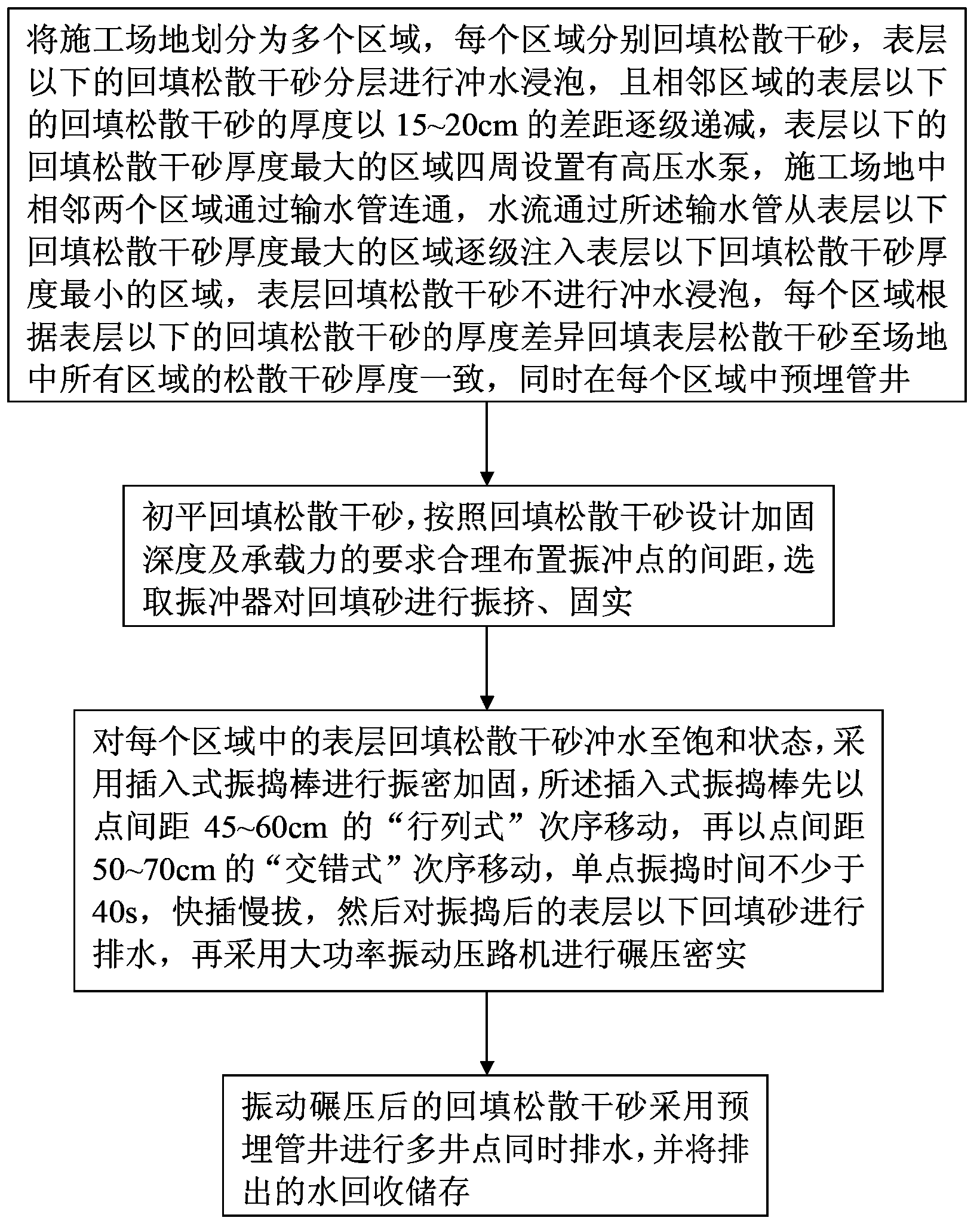
[0020] The invention provides a kind of dry sand pre-densified vibration foundation reinforcement method, comprising:

[0021] Step 1. Divide the construction site into several areas according to the scope of the construction site, surrounding transportation road conditions and construction period requirements, and control the area of ​​each area at 20,000 to 30,000 m 2 Clay masonry is used to separate the cofferdams between the areas, so as to facilitate the flushing operation in different areas, clean up the weak layer of the base debris, etc. After compaction and leveling, use dump trucks to transport loose dry sand to backfill each area separately , the coarse sand in the gravel is backfilled in the center of the area at 10,000 to 20,000 m 2 , the middle sand is backfilled in th...


PUM


Abstract

The invention relates to the technical field of foundation reinforcing treatment, in particular to a dry-sand preconsolidation vibrating foundation reinforcing method. The dry-sand preconsolidation vibrating foundation reinforcing method comprises the following steps of backfilling loose dry sand on a construction site, conducting water filling soaking on backfilled loose dry sand which is arranged below the surface layer in a layered mode, guaranteeing that water filling soaking is not conducted on surface-layer backfilled loose dry sand, embedding a tube well simultaneously, arranging the intervals of vibroflotation points, selecting a vibroflot to conduct vibro-densification and solidification on the backfilled sand, conducting water discharging on the backfilled sand after vibro-densification is conducted, conducting roller compaction densification through a high-power vibratory roller, and conducting water discharging on multiple well points. The dry-sand preconsolidation vibrating foundation reinforcing method improves the bearing capacity of the backfilled loose dry sand, effectively reduces the deformation amount of a foundation, improves the usable value of the surface-layer backfilled loose dry sand, and reduces production cost.

Description

technical field [0001] The invention relates to the technical field of foundation reinforcement treatment, in particular to a dry sand pre-densification vibration foundation reinforcement method. Background technique [0002] At home and abroad, for the foundation reinforcement of backfilling loose dry sand in large-area deep and thick layers, according to the traditional construction technology, vibrating compaction method or layered backfill rolling method is generally used. In recent years, watertight method has appeared in coastal areas, but each The construction technology has its deficiencies in the treatment of the above-mentioned backfill soil layers. The strength of the foundation surface in the range of 1-1.5m treated by the vibrating compaction method is low, and the surface soil needs to be excavated when the upper part is designed; the layered backfill rolling method is greatly affected by the rainfall weather, and after the rainfall, the backfilled sand needs t...

Claims


Application Information

Patent Timeline
Patent Type & Authority Applications(China)
IPC IPC(8): E02D3/054
Inventor 丁凤霞刘文东程书昌
Owner 化学工业第一勘察设计院有限公司
Why Eureka
Try Eureka