
Test device, test method and prediction method for tangential dynamic characteristics of bolted joint

A technology of bolted joints and dynamic characteristics, applied in the testing of machine/structural components, measuring devices, testing of mechanical components, etc. replacement effect

Inactive Publication Date: 2015-11-18
XI'AN UNIVERSITY OF ARCHITECTURE AND TECHNOLOGY
View PDF3 Cites 0 Cited by
  • Summary
  • Abstract
  • Description
  • Claims
  • Application Information

AI Technical Summary

Problems solved by technology

[0003] There are so many influencing factors, and their influencing laws are mostly non-linear, and the factors influence each other, so it is impossible to directly determine their influencing laws and degree of influence by means of theoretical analysis. Experimental research methods must be used to solve
In addition, due to the variety of bolt arrangements, it is difficult to obtain all the dynamic characteristics of bolted connection structures by experimental methods.
[0004] In order to predict the tangential dynamic characteristics of the bolt group structure with different bolt arrangements, and systematically study and prove the relationship between the tangential dynamic characteristics of the bolted connection structure and its basic influencing factors, a complete set of testing devices and methods are needed, and there is no such method yet. Correlation device for predicting tangential properties of bolted joints

Method used


Image

  • Test device, test method and prediction method for tangential dynamic characteristics of bolted joint
  • Test device, test method and prediction method for tangential dynamic characteristics of bolted joint
  • Test device, test method and prediction method for tangential dynamic characteristics of bolted joint

Examples


Embodiment Construction

[0035] The device for predicting the tangential dynamic characteristics of the bolt group of the present invention will be further described in detail below in conjunction with the working principle and the structural drawings.

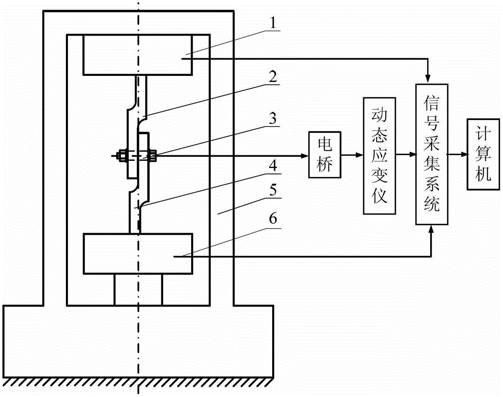
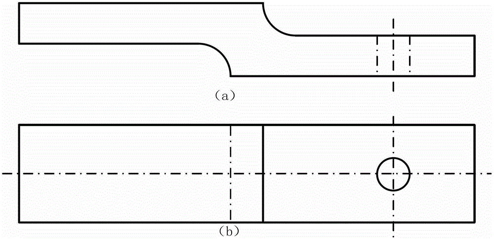
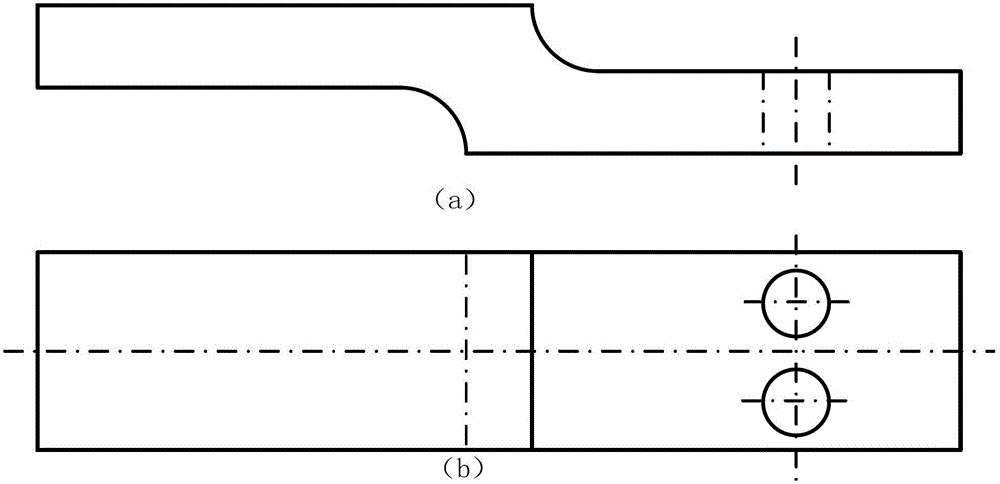
[0036] Such as Figure 1 to Figure 9 As shown in (b), a device for predicting the tangential dynamic characteristics of a bolt group structure, including a tensile testing machine 5, an upper specimen 2, a lower specimen 4, high-strength bolts 3, strain gauges, bridges, dynamic strain instrument, signal acquisition system and computer. Utilize a torque wrench to fix the upper fixture 1 of the upper specimen 2 and the tensile testing machine 5, and fix the lower specimen 4 and the lower clamp 6 of the tensile testing machine 5; To ensure the coaxiality, first clamp the lower test piece 4, after adjusting the upper fixture 1 of the tensile testing machine 5, clamp the upper test piece 2; along the center of the screw axis of the bolt 3, a Strain gauge...


PUM


Abstract

The invention discloses a test apparatus, a test method and a prediction method of bolting junction tangential dynamic characteristics. The test apparatus comprises a force tensile testing machine, an upper test piece, a lower test piece, bolts, strain gauges, a bridge, a dynamic strain indicator, a signal acquisition system and a computer. The upper test piece is fixed with an upper clamp of the force tensile testing machine, and the lower test piece is fixed with a lower clamp of the force tensile testing machine. The upper test piece and the lower test piece are fixed through the bolts. Each strain gauge is implanted at the centers of a screw axis of each bolt, and is connected with the bridge. The bridge is connected with the signal acquisition system through the dynamic strain indicator. Force and displacement of the force tensile testing machine are respectively sent to the signal acquisition system through a force sensor and a displacement sensor. The signal acquisition system is connected with the computer for transmitting the acquired bolt pre-tightening force and the data of the force and the displacement of the force tensile testing machine to the computer. The test apparatus is simple in structure, convenient for loading and unloading and easy to conduct repeated tests, and solves a problem that the retardation non-linear characteristic of the bolting junction is difficult to test.

Description

technical field [0001] The invention belongs to the field of mechanical design and manufacture, and in particular relates to a testing device, a testing method and a predicting method for the tangential dynamic characteristic of a bolt joint. Background technique [0002] The mechanical structure is a whole composed of many parts combined according to certain functional requirements, and bolt connection is one of the main forms. The structure connected by bolts is mainly composed of two parts: the joint surface and the bolted connection. Due to the nonlinear characteristics of the joint surface and the nonlinearity of the bolted connection due to factors such as clearance, dry friction, prestress, and initial deformation, the bolted connection structure has a great influence on the dynamic performance of the overall structure, and the mechanism is extremely complicated. There are many factors that affect the dynamic characteristics of the joint surface, and they are very co...

Claims


Application Information

Patent Timeline
Patent Type & Authority Patents(China)
IPC IPC(8): G01M13/00G01L5/24
Inventor 李玲蔡安江阮晓光林红惠旭升
Owner XI'AN UNIVERSITY OF ARCHITECTURE AND TECHNOLOGY
Learn More