
Camera system applicable to vacuum and cryogenic environment

A camera system and vacuum technology, applied in the field of camera systems, can solve the problems of damaged electronic components, electrolytic capacitors and other sealed components such as bursting and component failure, and achieve the effect of preventing overcooling or overheating

Inactive Publication Date: 2013-10-16
BEIHANG UNIV
View PDF5 Cites 10 Cited by
  • Summary
  • Abstract
  • Description
  • Claims
  • Application Information

AI Technical Summary

Problems solved by technology

[0004] First of all, the high vacuum environment may cause the sealed components such as electrolytic capacitors to burst from the inside, and the low voltage discharge in the high vacuum environment will also damage the electronic components;
[0005] Secondly, after the introduction of cryogenic liquids such as liquid nitrogen, the low temperature environment will also cause some components of the camera to fail

Method used


Image

  • Camera system applicable to vacuum and cryogenic environment

Examples


Embodiment Construction

[0023] The present invention will be further described below in conjunction with the accompanying drawings.

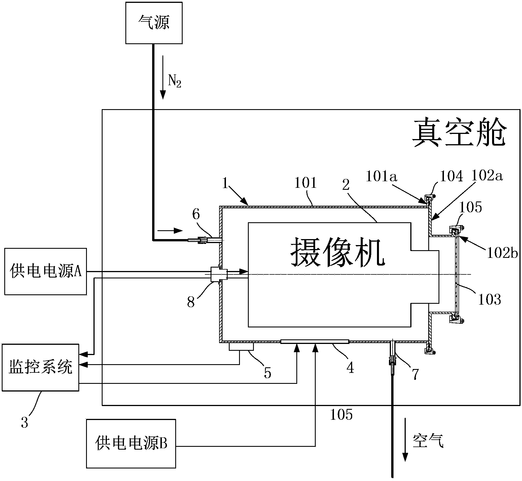
[0024] The camera system of the present invention includes a sealed box 1, a video camera 2, a monitoring system 3, a heating system composed of a heating plate 4 and a thermocouple 5, and a ventilation system composed of a ball joint inlet nozzle 6 and a ball joint air outlet nozzle 7. system, such as figure 1 shown.

[0025] The inside of the sealed box 1 is used to install the camera 2, the overall shape is consistent with the appearance of the camera 2, and the size is larger than the outer dimension of the camera 2, and it is composed of a box body A101, a box body B102 and an observation window 103, wherein the box body A101 is used to hold The body part of the camera 2 is a cylindrical structure with a closed bottom surface, and has an annular flange A101a on the top circumference. The box B102 is used to hold the lens part of the camera 2. It is also a cylind...


PUM


Abstract

The invention discloses a camera system applicable to vacuum and cryogenic environment. The camera system comprises a seal case, a camera, a monitoring system, a heating system and a ventilation system. The camera is arranged inside the seal case; the front end of the seal case is made of transparent material; the side walls of the seal case are provided with a vacuum aviation plug, a ball-head joint pipe air-inlet mouth and a ball-head joint pipe air-outlet mouth; the vacuum aviation plug is connected with a power supply A and the monitoring system which are outside a vacuum chamber as well as the camera which is inside the seal case via cables respectively; the ball-head joint pipe air-inlet mouth and the ball-head joint pipe air-outlet mouth are connected with an air source and air which are outside the vacuum chamber via connection pipes respectively; a heating sheet is pasted onto the outside wall of the seal case and is rubber sealed; a power supply B, which is outside the vacuum chamber, is connected with the heating sheet via a cable; a thermocouple is pasted on the outside wall of seal case; and a signal line of the thermocouple is connected with the monitoring system outside the vacuum chamber. The advantages of the camera system are that: physical damage, caused by the vacuum environment, to electronic components and the like of the camera is prevented; and problem of low voltage discharge in the vacuum environment for the camera is solved.

Description

technical field [0001] The invention relates to a camera system, in particular to a camera system suitable for vacuum and cryogenic environments. Background technique [0002] Aerospace is the embodiment of a country's scientific and technological level, and it has a wide and far-reaching impact on national and international politics, economy, military and social life. In order to study the vacuum performance of attitude control engines, many countries have established vacuum chambers to simulate vacuum environment for testing. The inner wall of the vacuum chamber is designed with a low-temperature cryogenic pump to increase the vacuum degree of the test, and low-temperature liquid such as liquid nitrogen is introduced to absorb the gas emitted by the engine during the test to increase the vacuum degree of the test. [0003] In order to observe the test process in the vacuum chamber, it is necessary to add a camera system, but the environment of the vacuum chamber will brin...

Claims


Application Information

Patent Timeline
IPC IPC(8): H04N5/225
Inventor 贺碧蛟张明星蔡国飙
Owner BEIHANG UNIV
Learn More