
Device and method for manufacturing tapered optical fiber

A technology for producing a tapered optical fiber and a device, which is applied to the coupling of optical waveguides and other directions, can solve the problems of complex device and long processing time, and achieve the effects of flexible design, improved work efficiency, and shortened processing time.

Inactive Publication Date: 2012-07-11
NINGBO UNIV
View PDF2 Cites 11 Cited by
  • Summary
  • Abstract
  • Description
  • Claims
  • Application Information

AI Technical Summary

Problems solved by technology

This method is not affected by external airflow and other factors, and can accurately control the parameters of the tapered optical fiber. However, this method usually requires a precise electronically controlled translation stage when used in the production of tapered optical fibers. The device is relatively complicated and the processing time is long.

Method used


Image

  • Device and method for manufacturing tapered optical fiber
  • Device and method for manufacturing tapered optical fiber
  • Device and method for manufacturing tapered optical fiber

Examples


Embodiment 1

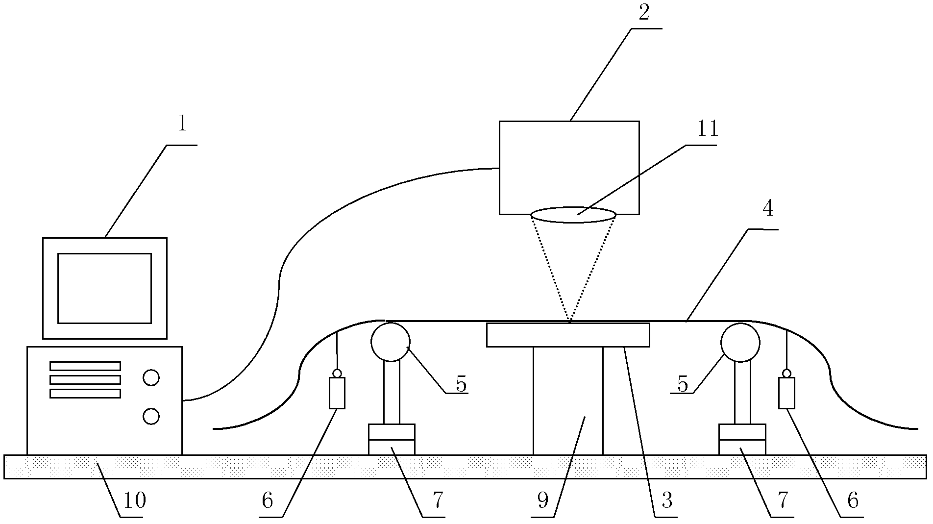
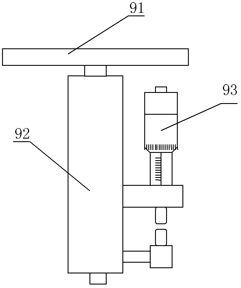
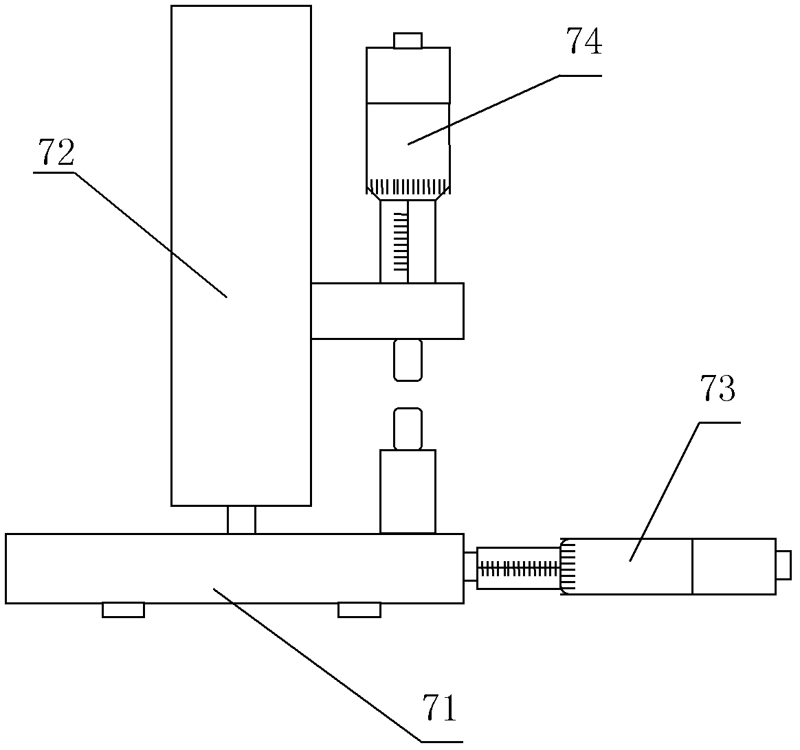
[0044] A kind of manufacturing device of tapered optical fiber, such as figure 1 As shown, it includes a computer terminal 1, a carbon dioxide laser 2, a scanning vibrating mirror 11, a metal-coated film mirror 3 with high reflectivity, a placement platform 9 for placing the metal-coated film mirror 3, two places distributed The two-dimensional precision adjustment frame 7 placed on both sides of the platform 9, two optical fiber fixtures 5 distributed on both sides of the placed platform 9 and used to fix the two ends of the processed optical fiber 4 respectively, and a pair of equal quality for hanging on the Both ends of the optical fiber 4 are processed to provide a continuous and constant tension weight 6 and an optical flat plate 10 for placing the above-mentioned various devices. The carbon dioxide laser 2 and the scanning galvanometer 11 are respectively connected to the computer terminal 1 and controlled by the computer terminal 1. , the scanning galvanometer 11 is lo...

Embodiment 2

[0055] This embodiment proposes a method for manufacturing a tapered optical fiber using the manufacturing device described in Embodiment 1. First, the processed optical fiber 4 used to make the tapered optical fiber is decoated and placed on the mirror surface of the metal-coated mirror 3, and then several pairs of weights 6 are suspended symmetrically on the two ends of the processed optical fiber 4, The height and the horizontal position of the optical fiber fixing member 5 are adjusted by the two-dimensional precision adjustment frame 7 so that the optical fiber part that has been stripped of the coating layer in the processed optical fiber 4 is in the focal plane of the focusing lens of the carbon dioxide laser 2, and the processed optical fiber 4 The axial direction is perpendicular to the movement track of the laser spot 8 output by the carbon dioxide laser 2, and the height of the metal-coated mirror 3 is adjusted by placing the platform 9 so that the mirror surface of ...

Embodiment 3

[0072] A method of manufacturing a tapered optical fiber using the manufacturing device described in Embodiment 1. In the manufacturing device described in Embodiment 1, the carbon dioxide laser 2 is a pulsed carbon dioxide laser with an output laser wavelength of 10.6 μm. The method of this embodiment can produce tapered optical fibers with different structural parameters by setting the working parameters of the carbon dioxide laser 2 and selecting weights 6 of different masses. It mainly includes the following steps:

[0073] ① Turn on the carbon dioxide laser 2, and set the working parameters of the carbon dioxide laser 2 in the computer terminal 1. The pulse frequency is set to 5KHz, the output power is set to 7.75W, and the residence time of the laser spot 8 acting on the processed optical fiber 4 is set to 700 μs, and the distance between two laser spots 8 is set to 1 μm.

[0074] ②Prepare a predetermined length of standard single-mode optical fiber (model G.652D) as th...


PUM


Abstract

The invention discloses a device and a method for manufacturing a tapered optical fiber. The device comprises an optical flat, a computer terminal, a carbon dioxide laser, a scanning galvanometer, a metal film plated reflector, a placing platform, two bi-dimensional accurate adjusting brackets, two optical fiber fixing parts and a plurality of pairs of weights. The placing platform is used for placing the metal film plated reflector, the two bi-dimensional accurate adjusting brackets are respectively arranged on two sides of the placing platform, the two optical fiber fixing parts are respectively fixed on the two bi-dimensional accurate adjusting brackets and are respectively used for fixing one of two ends of the processed optical fiber, the plurality of pairs of weights are used for suspending on the two ends of the processed optical fiber, the mirror surface of the reflector is right against an output end of the carbon dioxide laser, during usage, a portion to be processed with a coating layer removed in the processed optical fiber is enabled to tightly cling to the mirror surface of the reflector and is located on a focal plane of a focusing lens of the carbon dioxide laser, output laser spots of the carbon dioxide laser are controlled by the computer terminal, and the weights are quickly pulled after one scanning is completed to obtain the tapered optical fiber. Not onlythe processing time is shortened, but also physical damage to the optical fiber caused by long time action of the output laser spots on the optical fiber is avoided.

Description

technical field [0001] The invention relates to a manufacturing technology of an optical passive device and a special optical device, in particular to a manufacturing device and method of a tapered optical fiber. Background technique [0002] Tapered optical fiber refers to an optical device with a special optical waveguide structure with a tapered waist and a symmetrical double-cone transition region. Research hotspots at home and abroad. When light propagates in a tapered fiber, energy coupling and interference effects will occur between different modes, and a variety of optical components can be realized based on this principle. As a special optical device, tapered optical fiber has unparalleled advantages in micro-devices, and has been applied in the fields of full-wave coupler, near-field microscopic imaging, refractive index sensor, microcavity laser, supercontinuum light source, etc. widely used. [0003] The manufacturing method of the tapered optical fiber mainly...

Claims


Application Information

Patent Timeline
Patent Type & Authority Applications(China)
IPC IPC(8): G02B6/255
Inventor 周骏张琪陈金平阳明仰束磊谭晓玲
Owner NINGBO UNIV
Learn More