Granulating device for molten steel or iron slag
A technology for liquid steel slag and iron slag, which is applied in the field of granulation devices, can solve the problem of insufficient utilization of heat, and achieve the effects of simple structure, uniform particle size and good application prospect.
- Summary
- Abstract
- Description
- Claims
- Application Information
AI Technical Summary
Problems solved by technology
Method used
Image

Examples
Embodiment Construction
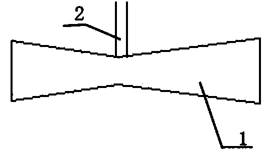
[0021] Examples such as figure 1 As shown, a granulation device for liquid steel slag or iron slag includes a combined nozzle 1 composed of a reducer and an expander, and a throat perpendicular to the combined nozzle 1 is arranged at the throat of the combined nozzle 1 The outer space of the combined nozzle 1 and the slag pipeline 2 has a cooling airflow.
[0022] When the molten steel slag or iron slag flows out of the pipeline, it is impacted and cooled by the high-speed airflow at the throat to form granulated slag, and the granulated slag sprayed out from the nozzle is mixed with the external cooling airflow for further cooling to make it solidify rapidly.
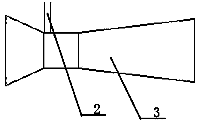
[0023] In the above embodiment, if figure 2 As shown, the combined nozzle can also be formed by a Venturi tube 3 .
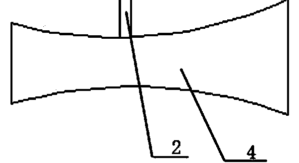
[0024] In the above embodiment, if image 3 As shown, the combined nozzle can also be composed of a Rafal nozzle 4 .
[0025] In the above embodiments, one or more slag pipelines 2 can be arrang...
PUM
 Abstract
Description
Claims
Application Information
 - R&D
- Intellectual Property
- Life Sciences
- Materials
- Tech Scout
- Unparalleled Data Quality
- Higher Quality Content
- 60% Fewer Hallucinations
Browse by: Latest US Patents, China's latest patents, Technical Efficacy Thesaurus, Application Domain, Technology Topic, Popular Technical Reports.
© 2025 PatSnap. All rights reserved.Legal|Privacy policy|Modern Slavery Act Transparency Statement|Sitemap|About US| Contact US: help@patsnap.com