

Six-shaft cement mixing pile machine
A cement-soil mixing pile and six-axis technology, which is applied to sheet pile walls, earthwork drilling, drilling equipment, etc., can solve the problems of small number of cement-soil mixing piles, high cost, and high cost, so as to improve construction quality and reduce equipment The effect of simple construction cost and equipment structure
Inactive Publication Date: 2013-10-23
SHANGHAI STRONG FOUND ENG
View PDF5 Cites 17 Cited by
- Summary
- Abstract
- Description
- Claims
- Application Information
AI Technical Summary
Benefits of technology
This patented device has several technical features that make it easier for workers to use them than current methods like hand mixers or screw drivers. It simplifies its design by connecting each individual drilling rod separately instead of just making up three separate components altogether. Additionally, this new method allows for more efficient jointing between different parts of the apparatus without requiring excessive effort from all involved during assembly process. Overall, these improvements lead to improved performance, reduced manufacturing times, lowered construction costs, increased durability, better overall results, and greater ease of operation over existing systems.
Problems solved by technology
This patented technical problem addressed in this patents relates to improving both strong and stable foundations during temporary building works without sacrificially replacing existing materials like sand bags due to their lower durability compared to other methods (such as steel bars). Additionally, current methods require longer downtime when forming more than once per job, leading to increased labor intensity and potential safety concerns associated with workers' compensation claims over long periods of use.
Method used
View moreImage
Smart ImageViewing Examples

Examples
Embodiment 2
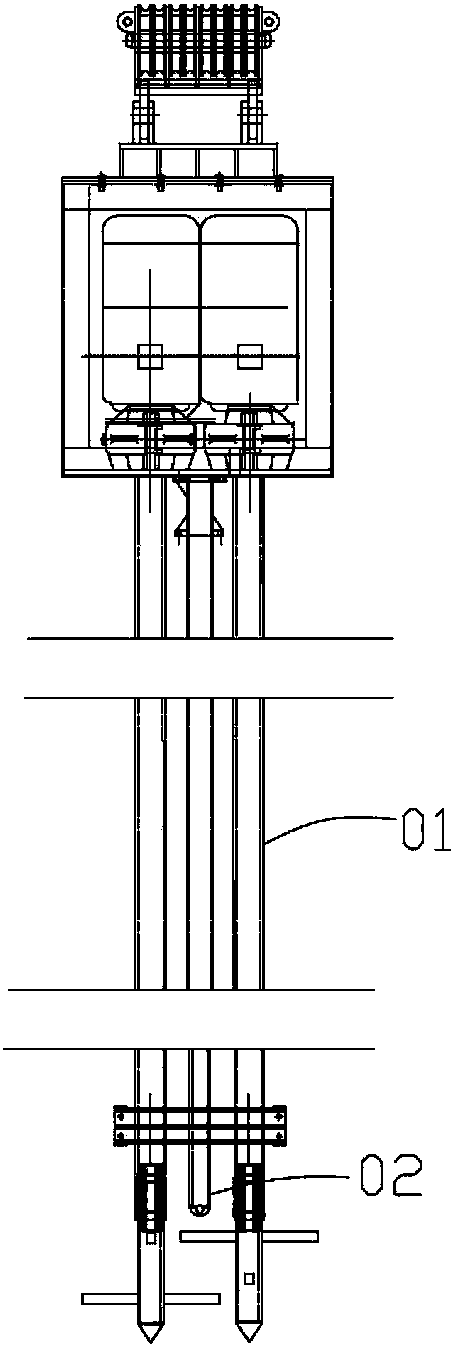
[0051] Example 2, see Figure 6 , the drill rod passes through the power box and extends upwards, the height of the pile frame does not need to be higher than the drill rod, so that the ultra-long drill rod can be drilled smoothly. All the other simultaneous embodiment 1.
Embodiment 3
[0052] Embodiment 3, see Figure 7, the drill rod is connected with the agitating drill bit 11 at the same height at the bottom of the drill rod, and the agitating drill bit 11 does not interfere with each other before starting to rotate, so when all the drill rods rotate synchronously at a uniform speed, they do not interfere with each other. All the other are with embodiment 1.
Login to View More PUM
| Property | Measurement | Unit |
|---|---|---|
| Length | aaaaa | aaaaa |
Abstract
The invention provides a six-shaft cement mixing pile machine. A power box is connected with six drill stems, the six drill stems are provided with a plurality of blades or vanes, and the six drill stems can directly spray concrete to finish construction of six cement stirring piles. Compared with a traditional mixing pile machine, the six-shaft cement mixing pile machine is large in the number of drill stems. The drill stems are provided with more blades or vanes and can directly spray concrete so as to remarkably improve construction efficiency, reduce labor cost, shorten work period, reduce mixing pile joints, improve construction quality and reduce construction cost.
Description
Login to View More Claims
Login to View More Application Information
Patent Timeline
 OwnerSHANGHAI STRONG FOUND ENG