Non-contact type gear tooth direction measuring method of laser vision distance measurement

A non-contact, visual ranging technology, used in measuring devices, optical devices, instruments, etc., can solve the problem of failure to meet the comprehensive detection requirements of gear accuracy, contact pressure and radius compensation, and easy to scratch the surface of the workpiece to be measured. and other problems, to achieve the effect of strong anti-interference ability, low hardware cost, and improved contact pressure

Inactive Publication Date: 2013-10-23
TIANJIN POLYTECHNIC UNIV
View PDF0 Cites 16 Cited by
  • Summary
  • Abstract
  • Description
  • Claims
  • Application Information

AI Technical Summary

Problems solved by technology

General enterprises only rely on the human eye to distinguish one by one under the microscope, the efficiency and accuracy are extremely low, and the human factors in the measurement results have a great influence
The measurement of three coordinate measuring machines mostly adopts contact measurement, which has defects such as slow speed, easy to scratch the surface of the workpiece to be measured, contact pressure and radius compensation, etc.
However, due to the complexity of gear forming and the variety of testing items, the system failed to meet the comprehensive testing requirements of gear precision

Method used


Image

  • Non-contact type gear tooth direction measuring method of laser vision distance measurement
  • Non-contact type gear tooth direction measuring method of laser vision distance measurement
  • Non-contact type gear tooth direction measuring method of laser vision distance measurement

Examples


Embodiment Construction

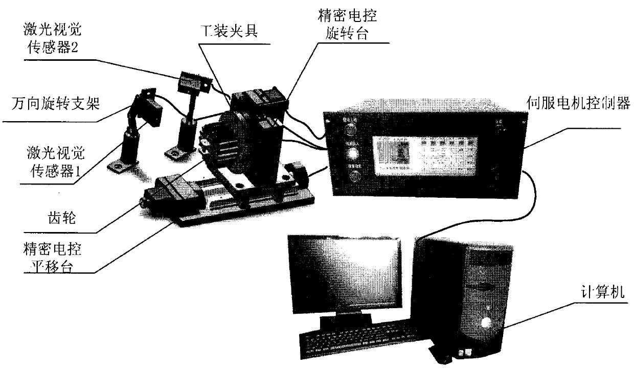
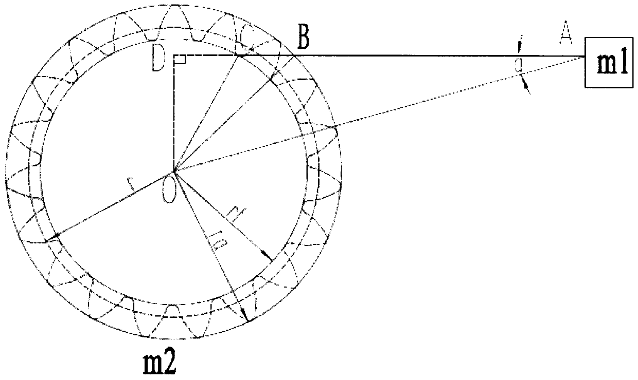
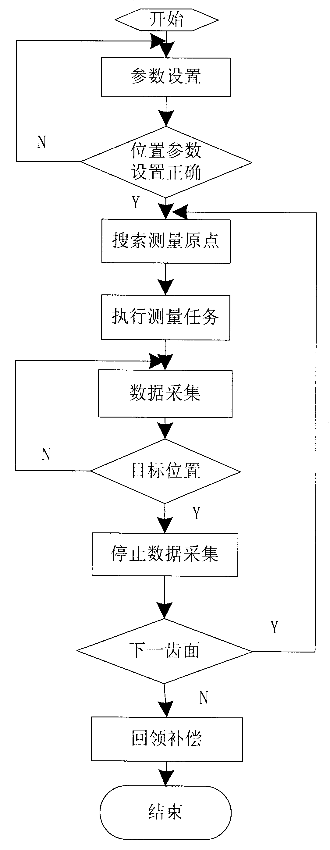
[0036] A non-contact gear tooth orientation measurement system based on laser vision distance measurement such as figure 1 shown. The precision electronically controlled translation stage is connected to the rotary table through an adapter plate, and the gear to be tested is fixed to the precision electronically controlled rotary table with a fixture to form a measuring workbench. Install two laser vision sensors of the same type on two universal rotating brackets, and fix them to one side of the workbench at a distance of 55mm to 75mm from the workpiece to be measured. Two laser vision sensors constitute an independent gear measurement system.

[0037] In order to improve the accuracy of the measurement results, it is necessary to calibrate the position of the system. The repeatability error of the sensor, the straightness of the precision electronically controlled translation stage, and the coaxiality between the fixture and the precision electronically controlled rotary t...


PUM


Abstract

The invention belongs to the field of non-contact type measurement of a gear and relates to a gear tooth direction measuring method based on laser vision sensors. According to the gear tooth direction measuring method disclosed by the invention, the two laser vision sensors are used as main measuring tools and a grating ruler obtains data; the establishment of a system is finished by combining accurate positioning movement of a precise translation platform and a rotary platform with the control of upper computer software of a computer. A system position relation is calibrated and a corresponding algorithm is used for calculating a reference circle position relation of the sensors and a gear. And then, a laser triangulation distance measurement principle is used for measuring gear tooth direction data. According to the gear tooth direction measuring method disclosed by the invention, on the basis of a low software cost, a non-contact type measuring method is used for reducing a system error between a tested workpiece and a measuring system, caused by contact pressure, and a random error. Compared with other measuring methods, the gear tooth direction measuring method has the advantages of strong anti-interference capability, fast measuring speed, high precision, simplicity in operation method and the like. The gear tooth direction measuring method disclosed by the invention can also be used for measuring other workpieces with complicated surface shapes.

Description

technical field [0001] The present invention relates to a non-contact gear tooth orientation measurement method for laser vision distance measurement. More specifically, the gear measurement method provided by the present invention uses two laser vision sensors to simultaneously obtain the tooth orientation data of the left and right tooth surfaces of the gear. , and automatically classify the gears according to the national standards according to the measured gear tooth data. Background technique [0002] According to whether it touches the surface of the workpiece to be tested, the gear detection methods can be roughly divided into two categories: contact measurement and non-contact measurement. General enterprises only rely on the human eye to distinguish one by one under the microscope, the efficiency and precision are extremely low, and the human factors in the measurement results have a great influence. The measurement of three coordinate measuring machines mostly ado...

Claims


Application Information

Patent Timeline
Patent Type & Authority Applications(China)
IPC IPC(8): G01B11/24
Inventor 宋丽梅杨燕罡覃名翠陈卓李大鹏唐欢
Owner TIANJIN POLYTECHNIC UNIV
Why Eureka
Try Eureka