System and method for monitoring output signals of an encoder

A technology of output signal and monitoring system, applied in the direction of converting sensor output, instrument, measuring device, etc., can solve the problems of increased manufacturing cost, deterioration detection, increased number of parts, etc., and achieve the effect of eliminating the waste of maintenance time and funds

Active Publication Date: 2013-10-23
DR JOHANNES HEIDENHAIN GMBH
View PDF5 Cites 10 Cited by
  • Summary
  • Abstract
  • Description
  • Claims
  • Application Information

AI Technical Summary

Problems solved by technology

[0005] On the other hand, there are many disadvantages as follows: In order to monitor the analog signal inside the encoder, a dedicated output line for maintenance is required, and a circuit for analog signal monitoring is additionally provided, and the number of parts increases or the structure becomes complicated, which reduces the manufacturing cost. increases, but becomes prone to failure, etc.
[0011] The problem to be solv

Method used


Image

  • System and method for monitoring output signals of an encoder
  • System and method for monitoring output signals of an encoder
  • System and method for monitoring output signals of an encoder

Examples


Embodiment 1

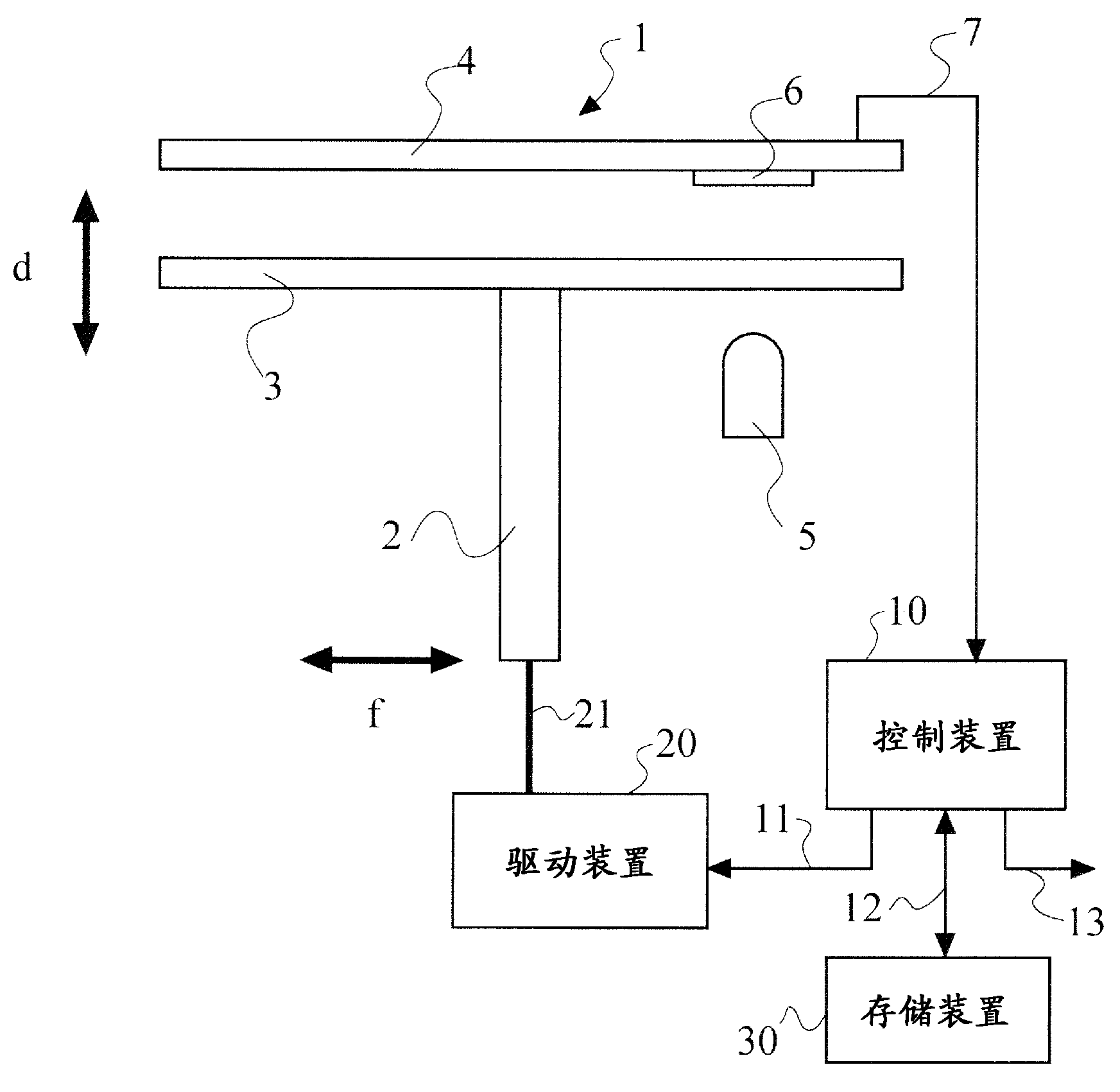
[0043] Next, an Example is shown and this invention is demonstrated more concretely. figure 1 It is a schematic diagram showing a configuration example of an encoder system as an embodiment of the present invention. In the figure, there is an encoder main body 1 for measuring the displacement, moving distance, etc. of the measurement object, a driving device 20 for the working equipment and the like as the measurement object, and controls the aforementioned The control device 10 for the operation of the driving device 20 and the storage device 30 for storing the basic operation set as the operation of the driving device 20 in association with the output data of the encoder at that time.

[0044] Encoder main body 1 has the encoder shaft 2 that is connected with the rotating shaft 21 of driving device 20 and follows the rotation motion of driving device and rotates, the disk-shaped symbol plate 3 that is installed on this encoder shaft 2, fixed symbol plate (not shown) shown),...

Embodiment 2

[0060] Next, along the image 3 The flow chart shown illustrates the method of the present invention.

[0061] First, the basic operation mode of the measurement object is set at the time of initial setting such as installation in the device or maintenance. This setting may be stored in a drive device or an encoder control device, a storage device, or the like, or may be determined in advance only as a basic operation pattern for repeated operations in the future ( S1 ). Next, the measurement object is made to move according to the set basic movement pattern ( S2 ). At this time, necessary parameters of the output signal output from the encoder main body are measured ( S3 ). Next, each of the obtained measurement data is stored in a storage device in association with the aforementioned basic operation pattern ( S4 ).

[0062] Then, if necessary, the measurement object is operated in the basic operation mode ( S5 ), and necessary parameters of the output signal output from t...


PUM


Abstract

To detect actual deterioration from digital pulse signals output from an encoder in which the wave period, duty cycle, phase difference and phase direction vary according to the operating speed, resolution and movement direction and are difficult to determine, which makes it difficult to detect deterioration, and to eliminate the wasted time and expense for the maintenance involved in taking the necessary measures. A system and a method for monitoring output signals of an encoder, in which an output signal output from an encoder body 1 corresponding to a basic operation pattern of an object 20 being measured which is set in an initial state is associated with the basic operation pattern and stored in a storage device 30; the object 20 being measured is then operated in accordance with the basic operation pattern at fixed intervals; an output signal output from the encoder body 1 at that time and output signal data in the initial state stored in the storage device 30 are compared, and a warning is output if the difference between the two signals is greater than a fixed magnitude.

Description

technical field [0001] The present invention relates to an encoder output signal monitoring system and an encoder output signal monitoring method for detecting deterioration of an encoder, wherein the encoder converts the state of a rotating disc or a linear scale into an electrical signal and measures an object to be measured amount of displacement or movement. Background technique [0002] An encoder converts, for example, the state of a rotating disc or a linear scale into an electrical signal. For example, in an optical rotary encoder, light emitted by a light-emitting element is transmitted through a rotating disk, and the signal received by a light-receiving element is converted into a rectangular-wave digital pulse output signal by a signal processing unit. [0003] Also, like other electronic equipment and precision equipment, encoders deteriorate over time and cannot maintain their original performance. The main causes of encoder deterioration are, mechanically, d...

Claims


Application Information

Patent Timeline
IPC IPC(8): G01D18/00
CPCG01D5/3473G01D5/24466G01D5/244G01D18/00
Inventor 山本猛山下守
Owner DR JOHANNES HEIDENHAIN GMBH
Why Eureka
Try Eureka