Sealing device for automobile cabin and HVAC air-vent air quantity and air door
A technology of sealing device and tuyere, which is applied in the direction of measuring device, vehicle test, and by measuring the rate of increase and deceleration of fluid, can solve the problems of poor mobility, low degree of automation, and large difference, so as to save capital, cost and space problems, increased automation, and improved accuracy
- Summary
- Abstract
- Description
- Claims
- Application Information
AI Technical Summary
Problems solved by technology
Method used
Image
Examples
specific Embodiment approach 1
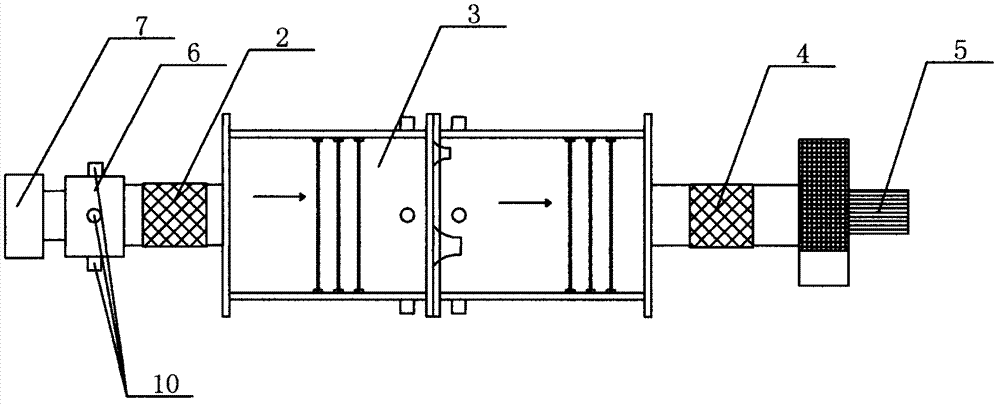
[0016] Specific implementation mode one: refer to figure 2 , the specific embodiment adopts the following technical solutions: it includes the first connecting air duct 2, the multi-nozzle air chamber wind tunnel 3, the second connecting air duct 4, the frequency conversion fan 5, the tuyere tooling 6, the HVAC air outlet 7, the air outlet static pressure The collection hole 9; the HVAC air outlet 7 is connected to the tuyere tooling 6, and the tuyere tooling 6 is uniformly provided with a plurality of tuyere static pressure collection holes 9, and the tuyere tooling 6 and the air inlet of the multi-nozzle air chamber wind tunnel 3 are connected through the first connection The air pipe 2 is connected, and the air outlet of the multi-nozzle air chamber wind tunnel 3 is connected with the air inlet of the frequency conversion fan 5 through the second connecting air pipe 4 .
[0017] The multi-nozzle air chamber wind tunnel 3, the frequency conversion fan 5, the electrical cont...
specific Embodiment approach 2
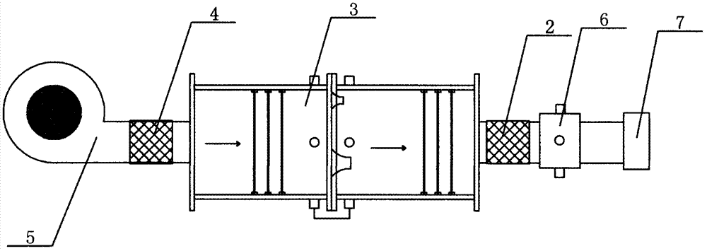
[0020] Specific implementation mode two: refer to image 3 The difference between this specific embodiment and specific embodiment 1 is that the tuyere tooling 6 and the air outlet of the multi-nozzle air chamber wind tunnel 3 are connected through the first connecting air pipe 2, and the multi-nozzle air chamber wind tunnel The air inlet of 3 is connected with the air outlet of frequency conversion fan 5 through the second connecting air duct 4, and other components and connection relations are the same as those of the second embodiment.
specific Embodiment approach 3
[0021] Specific implementation mode three: refer to Figure 4 , The difference between this specific embodiment and the specific embodiment one is that it includes the first connecting air duct 2, the multi-nozzle air chamber wind tunnel 3, the second connecting air duct 4, the frequency conversion fan 5, the door tooling 8, the static pressure Acquisition pipe 9; door tooling 8 is arranged at the door glass of the test vehicle, and a static pressure acquisition tube 9 is arranged in the test vehicle, and the door tooling 8 is connected to the air inlet of the wind tunnel 3 of the multi-nozzle air chamber through the first connecting air pipe 2 , the air outlet of the multi-nozzle air chamber wind tunnel 3 is connected with the air inlet of the frequency conversion fan 5 through the second connecting air pipe 4 .
PUM
 Abstract
Description
Claims
Application Information
 - R&D
- Intellectual Property
- Life Sciences
- Materials
- Tech Scout
- Unparalleled Data Quality
- Higher Quality Content
- 60% Fewer Hallucinations
Browse by: Latest US Patents, China's latest patents, Technical Efficacy Thesaurus, Application Domain, Technology Topic, Popular Technical Reports.
© 2025 PatSnap. All rights reserved.Legal|Privacy policy|Modern Slavery Act Transparency Statement|Sitemap|About US| Contact US: help@patsnap.com


