Combined dresser and its manufacturing method and chemical mechanical polishing method

A manufacturing method and trimmer technology, applied in semiconductor/solid-state device manufacturing, electrical components, circuits, etc., and can solve problems such as height differences

Inactive Publication Date: 2015-08-19
RITEDIA CORPORATION
View PDF4 Cites 0 Cited by
  • Summary
  • Abstract
  • Description
  • Claims
  • Application Information

AI Technical Summary

Problems solved by technology

[0008] However, the used grinding cusps of the above-mentioned patent applications need to use diamond abrasive grains with higher regularity in shape, and the crystal surface coverage of this crystal form is very high (such as greater than 50% of the surface is a crystal growth surface), otherwise when used Sharp diamonds with low crystalline surface coverage can cause excessive height differences

Method used


Image

  • Combined dresser and its manufacturing method and chemical mechanical polishing method
  • Combined dresser and its manufacturing method and chemical mechanical polishing method
  • Combined dresser and its manufacturing method and chemical mechanical polishing method

Examples


preparation example 1

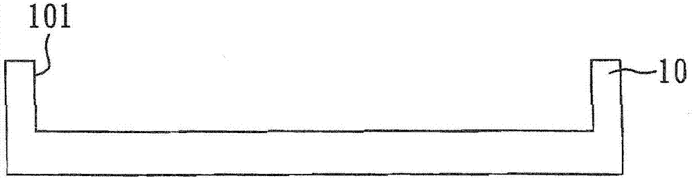
[0063] refer to Figure 1A to Figure 1G , a schematic flow chart of its manufacturing combined trimmer.

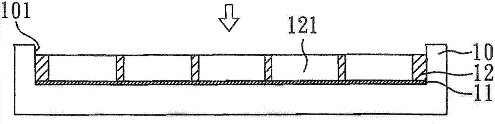
[0064] First, if Figure 1A As shown, a first mold 10 is provided, and the first mold 10 has an opening 101 . Next, if Figure 1B As shown, a temporary adhesive layer 11 is formed on the surface of the opening 101 of the first mold 10, and then a second mold 12 is placed on the surface of the temporary adhesive layer 11, so that the second mold 12 is placed on the opening of the first mold 10 101 , so the temporary adhesive layer 11 is sandwiched between the second mold 12 and the first mold 10 , wherein the second mold 12 has a plurality of holes 121 . In this preparation example, the temporary adhesive layer 11 is a double-sided adhesive tape.

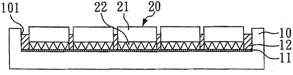
[0065] like Figure 1C and Figure 1G As shown, a grinding unit 20 is set in each hole 121 of the second mold 12, wherein each grinding unit 20 includes a plurality of grinding particles 22 (each grinding particle 22 has at...

preparation example 2

[0073] refer to Figure 2A to Figure 2G , which is a schematic flow chart of manufacturing a combined trimmer.

[0074] First, if Figure 2A As shown, a second mold 12 is provided, the second mold 12 has 12 holes 121 , and the holes are arranged on the outer ring of the second mold 12 . Next, if Figure 2B As shown, the second mold 12 is placed on the surface of a first mold 10 .

[0075] like Figure 2C As shown, in each hole 121 of the second mold 12 , a grinding unit 20 is provided, wherein the working surface of the grinding unit 20 (the surface with the sharp point of grinding) faces the surface of the first mold 10 . In this preparation example, the grinding unit 20 is similar to that described in preparation example 1. Then, if Figure 2D As shown, glue is dispensed on the opposite side of the sharp point of each grinding unit 20 to form an adhesive layer 23 with adjustable thickness. Next, if Figure 2E As shown, a bottom substrate 24 is flatly pressed on the a...


PUM


Abstract

The present invention is about a combined trimmer, comprising: a bottom substrate; a plurality of grinding units arranged at a surface of the bottom substrate, wherein the each grinding unit comprises a plurality of grinding sharp points and a binding agent layer for fixing the grinding sharp points; and an adhesive layer with an adjustable thickness for fixing the grinding units to the surface of the bottom substrate, wherein height difference between a first high point and a second high point in the grinding sharp points protruded from a predetermined plane is less than 10 micrometer, height difference between the first high point and a tenth high point is less than 20 micrometer, height difference between the first high point and a hundredth high point is less than 40 micrometer, and the height of the first high point protruded from the binding agent layer is greater than 50 micrometer. The present invention is also about a manufacturing method and a chemical mechanical polishing method of the combined trimmer.

Description

technical field [0001] The present invention relates to a combined dresser, its manufacturing method, and a chemical-mechanical planaization (CMP) method using it, especially a combined dresser suitable for polishing the surface of a semiconductor wafer, and its A manufacturing method, and a chemical mechanical polishing method using the same. Background technique [0002] For the fine copper circuit or interlayer tungsten circuit on the surface of the silicon wafer, and even the oxide film dielectric layer of the insulating circuit, it is necessary to polish the surface to facilitate subsequent process steps. At present, in the process of manufacturing integrated circuits (Interconnected Circuits, ICs) on semiconductor wafers, the polishing technology that attracts the most attention is chemical-mechanical polishing (chemical-mechanical Planaization, CMP). Polished surface. [0003] During the chemical mechanical polishing process, the slurry is stably and uniformly trans...

Claims


Application Information

Patent Timeline
Patent Type & Authority Patents(China)
IPC IPC(8): H01L21/768
Inventor 宋健民叶文挺
Owner RITEDIA CORPORATION
Why Eureka
Try Eureka