Half-wave dipole array element and micro-strip array antenna formed by same

A technology of half-wave arrays and microstrip arrays, applied to antennas, antenna arrays, electrical components, etc., can solve problems such as low gain, inflexibility of passive detection antennas, and poor directivity

Inactive Publication Date: 2013-10-23
LUOHE VOCATIONAL TECH COLLEGE
View PDF4 Cites 3 Cited by
  • Summary
  • Abstract
  • Description
  • Claims
  • Application Information

AI Technical Summary

Problems solved by technology

[0003] The amplitude of each antenna in the traditional mechanical scanning or phased array is un

Method used


Image

  • Half-wave dipole array element and micro-strip array antenna formed by same
  • Half-wave dipole array element and micro-strip array antenna formed by same
  • Half-wave dipole array element and micro-strip array antenna formed by same

Examples


Embodiment Construction

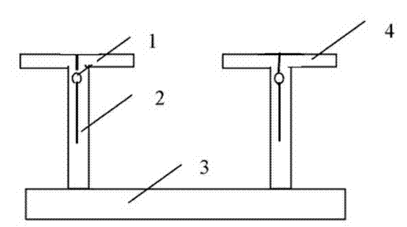
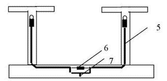
[0021] as attached Figure 1~4 As shown, a half-wave array element includes a copper-clad substrate 3, two half-wave arrays 4 are arranged on the substrate 3, and the front of the half-wave array 4 is provided with an impedance matching opening 1 and an impedance matching slot 2. There is a transmission microstrip line 5 on the back of the half-wave array element 4. The upper end of the transmission microstrip line 5 passes through the impedance matching opening 1 and is connected to the impedance matching slot 2. The lower end of the transmission microstrip line 5 is connected to the feed interface 7. , the lower end of the transmission microstrip line 5 is also connected with a matching resistor 6 .

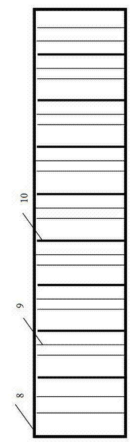
[0022] A microstrip array antenna includes a frame 8, a plurality of half-wave array elements are installed in the frame 8, and two reflectors 9 are arranged between two adjacent half-wave array elements 10.

[0023] The frame 8 is an aluminum alloy frame, and the reflector 9...


PUM


Abstract

The invention discloses a half-wave dipole array element and a micro-strip array antenna formed by the half-wave dipole array element. The array element comprises a copper-coated substrate, wherein two half-wave dipoles are arranged on the substrate; impedance matching holes and impedance matching slots are arranged in the front surfaces of the half-wave dipoles; transmission micro-strip lines are arranged on the back surfaces of the half-wave dipoles; and the upper ends of the transmission micro-strip lines are connected with the impedance matching slots after passing through the impedance matching holes, and the lower ends of the transmission micro-strip lines are connected with feed interfaces and matching resistors. According to the scheme, the coalition of sampled signals of the antenna are completed through a processor, the amplitudes and phase positions of micro-strip elements in multiple micro-strip arrays are regulated by utilizing a digital signal processing technology, a needed directional diagram is formed in space, and a mechanical rotating system is no longer needed.

Description

technical field [0001] The invention relates to a radio wave receiving device, in particular to an antenna. Background technique [0002] An antenna (antenna) is a transformer that converts a guided wave propagating on a transmission line into an electromagnetic wave propagating in an unbounded medium (usually free space), or vice versa. A component used in radio equipment to transmit or receive electromagnetic waves. Engineering systems such as radio communication, broadcasting, television, radar, navigation, electronic countermeasures, remote sensing, and radio astronomy, which use electromagnetic waves to transmit information, rely on antennas to work. In addition, in terms of transmitting energy with electromagnetic waves, non-signal energy radiation also requires antennas. Generally, antennas are reversible, that is, the same antenna can be used as both a transmitting antenna and a receiving antenna. The basic characteristic parameters of the same antenna as transmit...

Claims


Application Information

Patent Timeline
IPC IPC(8): H01Q1/36H01Q13/08H01Q19/10H01Q21/00H01Q3/28H01Q3/30
Inventor 张平川王新娜齐伟民高倩许兴广张超英张哲童
Owner LUOHE VOCATIONAL TECH COLLEGE
Why Eureka
Try Eureka