Novel high current switching control device

A control device and high-current technology, which is applied in the direction of circuit devices, electrical components, emergency power supply arrangements, etc., can solve the problems of high equipment costs and complex structures, so as to ensure power supply safety, simple system structure, and reduce system volume Effect

Active Publication Date: 2013-10-23
AVIC TECH XIAMEN ELECTRIC POWER TECH CO LTD
View PDF2 Cites 3 Cited by
  • Summary
  • Abstract
  • Description
  • Claims
  • Application Information

AI Technical Summary

Problems solved by technology

[0002] The existing high-power switching devices are all completed by two static switches, which are generally composed of thyristors, and their conduction voltage drop is generally about 2V. In a high-current power system, if a current of 1

Method used


Image

  • Novel high current switching control device

Examples


Embodiment 1

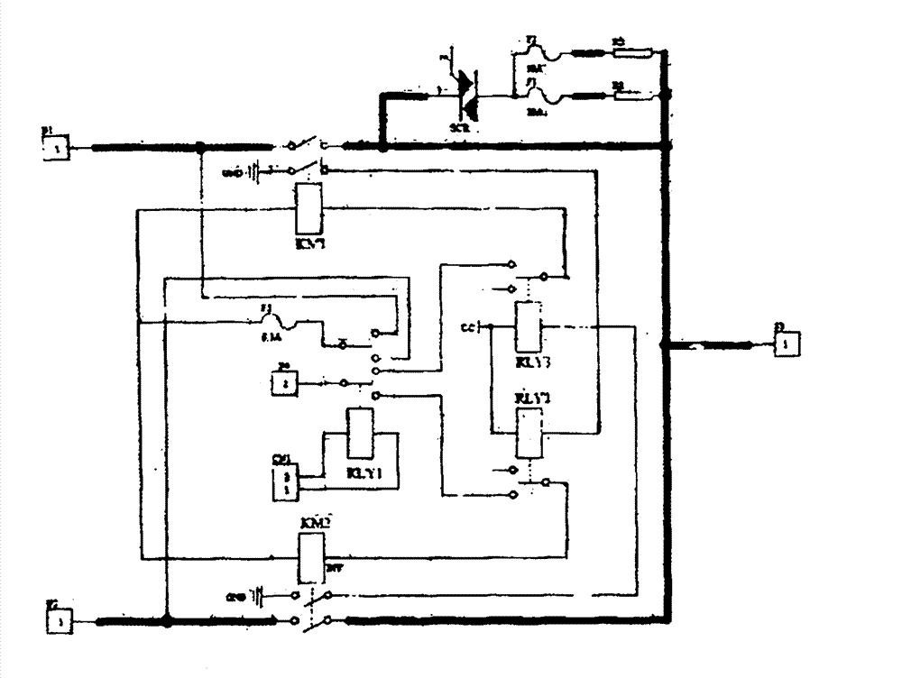
[0015] This embodiment is a switching device applied to high-power UPS (uninterruptible power supply), which is composed of AC contactors KM1, KM2, power resistors R1, R2, thyristor SCR and relays RLY1, RLY2, RLY3; relay RLY1 is used to control and select KM1 Pull-in or KM2 pull-in, that is, switch between bypass and inverter output; both contactors are attached with a normally open auxiliary contact, and the power circuits of their respective control coils pass through two auxiliary interlock relays RLY1 and RLY2 respectively The normally closed contacts of the relays RLY1 and RLY2 respectively pass through the normally open contacts of the two contactors to form a double electromechanical interlock control device to ensure that the two power supplies are switched at the moment of switching. safety and reliability.

[0016] In the early stage of power-on, all contactors and relays are in the released state; after power-on, the bypass live wire 1 passes through RLY1→F3→KM1 coi...


PUM


Abstract

The invention discloses a novel high current switching control device and belongs to a high-power current control device. The novel high current switching control device is composed of alternating-current contactors KM1 and KM2, a switching control relay RLY1, auxiliary interlocking relays RLY2 and RLY3, a silicon controlled rectifier SCR and current-limiting resistors R1 and R2. The novel high current switching control device is characterized in that the alternating-current contactors and the relays are open in an early stage of powering on; and the device has three states of being powered on, being switched from bypass output to inverter output and being switched from inverter output to bypass output. A switching compensation mechanism is introduced on the basis of a high-power switching device to ensure power supply safety of electric equipment and prolong the electrical life of a contact point. The novel high current switching control device has the advantages of being simple in structure, capable of realizing zero loss, energy-saving and environment-friendly, higher in operation efficiency, smaller in size, high in reliability and the like.

Description

technical field [0001] The invention relates to a high-power current control device, in particular to a novel high-current switching control device. Background technique [0002] The existing high-power switching devices are all completed by two static switches, which are generally composed of thyristors, and their conduction voltage drop is generally about 2V. In a high-current power system, if a current of 100A passes through, then Loss = 100A × 2V = 200W, it is necessary to install a heat dissipation device and a heat dissipation air duct on the SCR to prevent it from burning out, which will increase the equipment cost and complicate the structure. Therefore, overcoming the defective that existing product exists has become the task of top priority. Contents of the invention [0003] In order to overcome the shortcomings of the existing products, the object of the present invention is to provide a large current switching control device with simple structure, convenient ...

Claims


Application Information

Patent Timeline
IPC IPC(8): H02J9/06
CPCY02B70/30Y04S20/20
Inventor 林东权陈文全林火土
Owner AVIC TECH XIAMEN ELECTRIC POWER TECH CO LTD
Why Eureka
Try Eureka