
Synchronous belt type cold rolling forming machine and cold rolling pipemaking machine

A technology of forming machine and synchronous belt, applied in the direction of metal rolling stand, metal rolling mill stand, metal rolling, etc., can solve problems such as large workload, and achieve the effect of reducing cost and low noise

Active Publication Date: 2013-10-30
AIDA ENG LTD
View PDF6 Cites 4 Cited by
  • Summary
  • Abstract
  • Description
  • Claims
  • Application Information

AI Technical Summary

Problems solved by technology

In addition, since no universal joint is used between the center support 372 and the roll forming support 310, if the distance between the supports needs to be changed according to the specifications of the product, it needs to be changed again in accordance with the distance between the supports in the box 350. The distance between the brackets of the center bracket 372, as a result, in the center bracket 372, there is the problem that the universal joint 384 between the center bracket 372 and the worm reducer 380 must be adjusted again
That is, in Figure 11 In the conventional molding unit 303 shown, there is a problem that the amount of work required for changing the distance between the supports is large.

Method used


Image

  • Synchronous belt type cold rolling forming machine and cold rolling pipemaking machine
  • Synchronous belt type cold rolling forming machine and cold rolling pipemaking machine
  • Synchronous belt type cold rolling forming machine and cold rolling pipemaking machine

Examples


Embodiment Construction

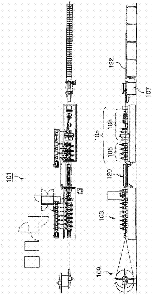
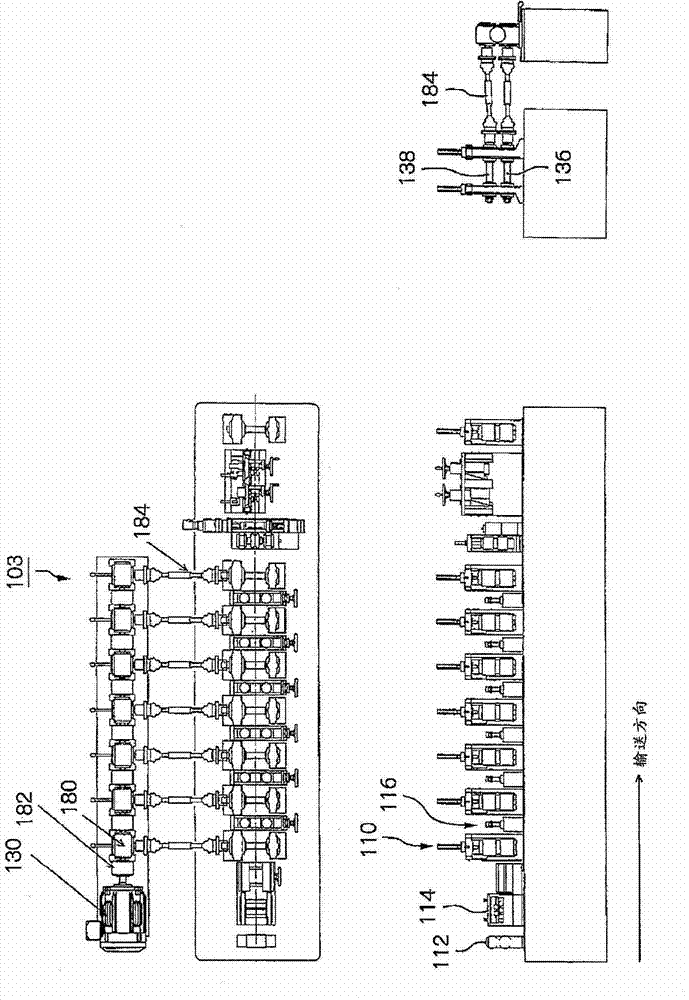
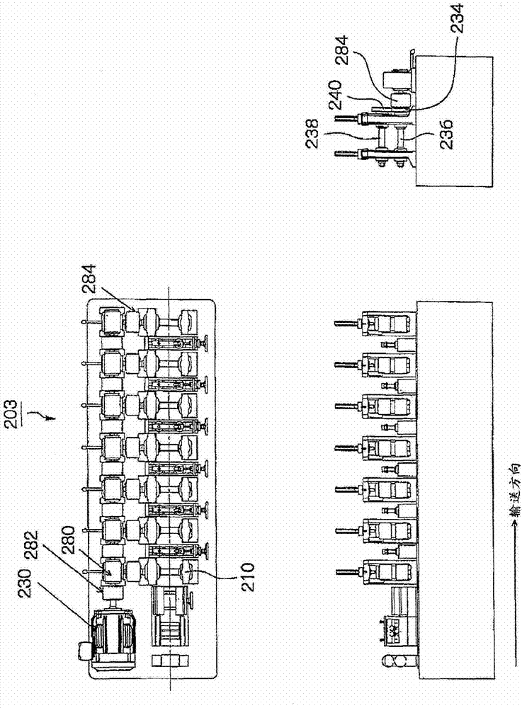
[0040] Hereinafter, modes for implementing the present invention will be described with reference to the drawings. Figure 4 It is an overall view of a cold rolling tube mill 1 as an example of the cold rolling forming machine of the first embodiment, Figure 5 is extracted Figure 4 A view of a part of the forming section 3 of the cold rolling tube mill 1 shown. Such as Figure 5 As shown, in the first embodiment, the forming unit 3 includes seven roll forming stands 10 and six side roll stands 16 as an example of a stand mechanism.

[0041] Composition of cold rolling tube machine

[0042] Figure 4 The shown cold rolling pipe machine 1 is configured to have: a forming part 3 for forming a billet into a predetermined shape; a cooling table 20 as an example of a cooling part for cooling the formed billet through water; Correction unit 5; mobile cutting machine 7. The forming part 3 has a welding part 4 for welding a butt part of a tubular blank. The straightening unit ...


PUM


Abstract

Provided is a cold rolling forming machine which can provide low noises and can retain the setting environment in a cleaning state without the need for grease in a power transmission mechanism. The cold rolling pipemaking machine (1) is provided with multiple stages of roller forming supports (10) which are arranged on the conveying direction and perform cold rolling forming on blanks in stages. Each stage of each roller forming support includes a driving belt pulley (34) driven by a driving motor; a lower roller being squarely to the conveying direction of the blanks and performing the cold rolling forming on the blanks; a lower roller shaft directly connected with the driving belt pulley and arranged on the lower roller; an upper roller being opposite to the lower roller over the blanks and performing the cold rolling forming on the blanks together with the lower roller; an upper roller shaft arranged on the upper roller; a driven belt pulley directly connected with the upper roller shaft; a synchronous belt wound on the driving belt pulley and the driven pulley to transmit the rotating force of the driving belt pulley to the driven belt pulley, and an assist belt pulley wound on the synchronous belt and being capable of adjusting the position of the driven belt pulley with respect to the driven belt pulley.

Description

technical field [0001] The invention relates to a synchronous belt cold rolling forming machine, a cold rolling pipe machine, and a support mechanism. Background technique [0002] As a technique disclosed in a publication providing a cold rolling forming apparatus capable of forming a plurality of products with different dimensions, plate thicknesses, and cross-sectional shapes by the same forming roll, there is, for example, the technique disclosed in Patent Document 1. [0003] In this technology, it is disclosed that a plurality of first and second movable roll forming supports are erected on the first and second movable tables on the base, so that the upper and lower roller shafts are erected on the first and second rollers in the erected state. 1. Extending between the second movable roll forming brackets, the upper and lower roll shafts are supported on the second movable roll shaft through the bearing mechanism through the upper sleeve and the lower sleeve that can m...

Claims


Application Information

Patent Timeline
IPC IPC(8): B21B17/14B21B35/04B21B31/02B21B37/48B21C37/08
Inventor 万殿贵志内田文法安田隆德
Owner AIDA ENG LTD
Learn More