
Tube bundle supporting member for shell-and-tube heat exchanger

A technology for shell-and-tube heat exchangers and supports, which is applied in the direction of heat exchanger shells, heat exchange equipment, lighting and heating equipment, etc., and can solve the problems of reduced number of pipes, loose pipe structure, and difficulty in ensuring manufacturing accuracy, etc. , to achieve the effect of increasing compactness, solving edge leakage, and improving overall heat exchange efficiency

Active Publication Date: 2013-10-30
YORK WUXI AIR CONDITIONING & REFRIGERATION CO LTD +1
View PDF6 Cites 7 Cited by
  • Summary
  • Abstract
  • Description
  • Claims
  • Application Information

AI Technical Summary

Problems solved by technology

However, there are the following disadvantages: the pipe layout structure is loose, and the number of pipes is small; the triangular pipe layout must increase the tube spacing to meet the requirements of the strength and stiffness of the baffle rod; the manufacturing accuracy is not easy to guarantee; The diameter of the tube and the baffle rod is small, and the rigidity is not easy to guarantee; the area where the tube is not arranged needs to be filled with a fake tube, which increases the equipment manufacturing cost; there is a large leakage area between the edge of the tube layout area and the baffle ring; the baffle ring occupies Larger space is provided, and the number of pipes is reduced
However, there are the following disadvantages: the triangular pipe layout must increase the distance between the pipes to meet the strength and rigidity requirements of the hole edge of the support; Leakage flow area; no solution proposed for non-complete holes; flow area cannot be adjusted after tube spacing is determined

Method used


Image

  • Tube bundle supporting member for shell-and-tube heat exchanger
  • Tube bundle supporting member for shell-and-tube heat exchanger
  • Tube bundle supporting member for shell-and-tube heat exchanger

Examples


Embodiment approach

[0041] Technical terms used in this invention

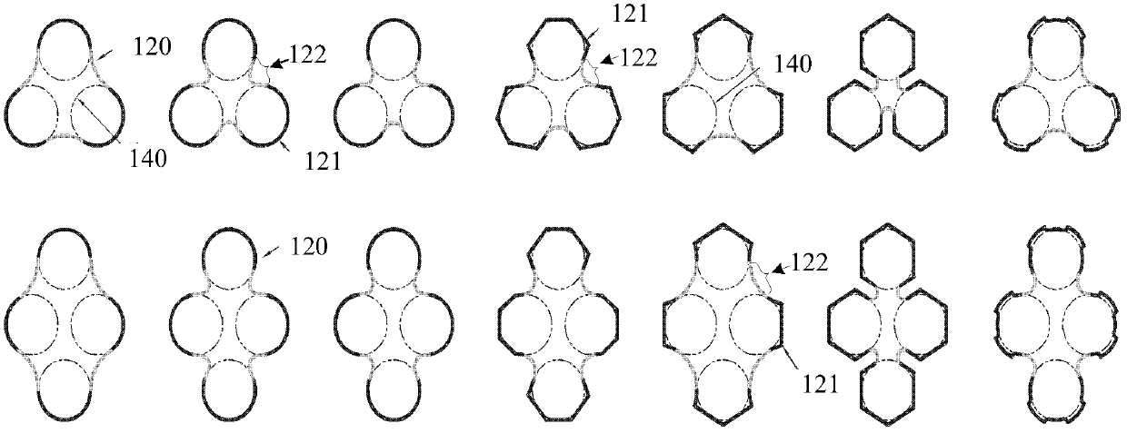
[0042] Heat exchange tube circle: refers to the closed contour formed by projecting the outer wall of the heat exchange tube onto a plane perpendicular to the axis of the heat exchange tube. A circle represents a heat exchange tube.

[0043] Tube hole circle: refers to the cross-sectional closed contour line of the hole used to support the heat exchange tube on the traditional arcuate support plate.

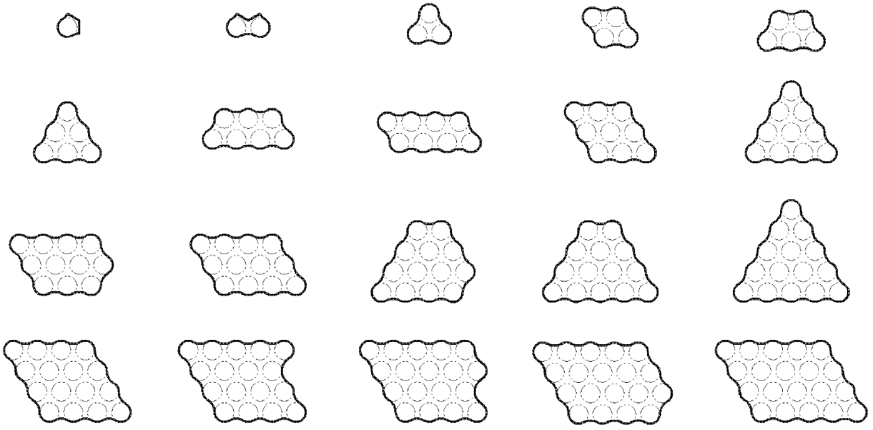
[0044] Basic pipe layout unit: refers to the triangle that determines the basic size of the heat exchange tube arrangement, and the apex of the triangle is the center of the heat exchange tube circle.

[0045] Adjacent pipe hole circles: refer to any two pipe hole circles in the basic pipe layout unit.

[0046] Support hole: refers to a hole that can accommodate at least one heat exchange tube, and the hole can at least limit at least one lateral movement of one heat exchange tube.

[0047] Standard support hole: refers to the ...


PUM


Abstract

The invention relates to a tube bundle supporting member for a shell-and-tube heat exchanger. The tube bundle supporting member comprises supporting holes. The supporting holes further include standard supporting holes and auxiliary supporting holes. Supporting lines and connecting lines identical in number are sequentially connected in an adjacent mode to form the sealing contour lines of the cross sections of the supporting holes. The tube bundle supporting member is characterized in that the connecting lines are concave curves formed by line segments or line segments and camber lines or camber lines, each standard supporting hole at least comprises one basic pipe distribution unit formed by three adjacent heat exchange tubes, each auxiliary supporting hole can at least accommodate one heat exchange tube, the number of the heat exchange tubes accommodated in one auxiliary supporting hole is less than that of the heat exchange tubes accommodated in one standard supporting hole. By the tube bundle supporting member, the problem of flow leakage at the edge of a tube distribution area is solved, tube distribution compact degree is increased, and overall heat exchange efficiency is improved.

Description

technical field [0001] The invention relates to the field of heat exchangers, in particular to a tube bundle support for a shell-and-tube heat exchanger. Background technique [0002] Tube bundles are mainly used in shell and tube heat exchangers. The shell-and-tube heat exchanger includes a tube side and a shell side, and the shell side is mainly composed of a cylindrical shell, a tube sheet, a tube bundle and a support for supporting the heat exchange tube. [0003] The heat exchange tubes have a certain length. In order to prevent the heat exchange tubes from generating large deflection, it is necessary to arrange support members at a certain distance along the length direction of the tube bundle. After a traditional support with a circular support hole is arranged in the length direction of the tube bundle, the fluid in the shell side is prevented from flowing along the axial direction of the tube bundle. In order to make the shell-side fluid flow from one end of the t...

Claims


Application Information

Patent Timeline
Patent Type & Authority Applications(China)
IPC IPC(8): F28F9/013B21D28/34B26F1/14B29C45/26B21C25/02B29C47/12B22C9/26B29C48/30
Inventor 潘建尧肖青松朱文政苏秀平李金良
Owner YORK WUXI AIR CONDITIONING & REFRIGERATION CO LTD
Learn More