Puncture needle for ultrasound
An ultrasonic and puncture needle technology, applied in the field of ultrasonic puncture needles, can solve the problems of accurately sending substances to the concerned parts and difficult to use and adjust
- Summary
- Abstract
- Description
- Claims
- Application Information
AI Technical Summary
Problems solved by technology
Method used
Image
Examples
no. 1 approach )
[0066] The ultrasonic puncture needle of this embodiment is used in combination with an ultrasonic endoscope.
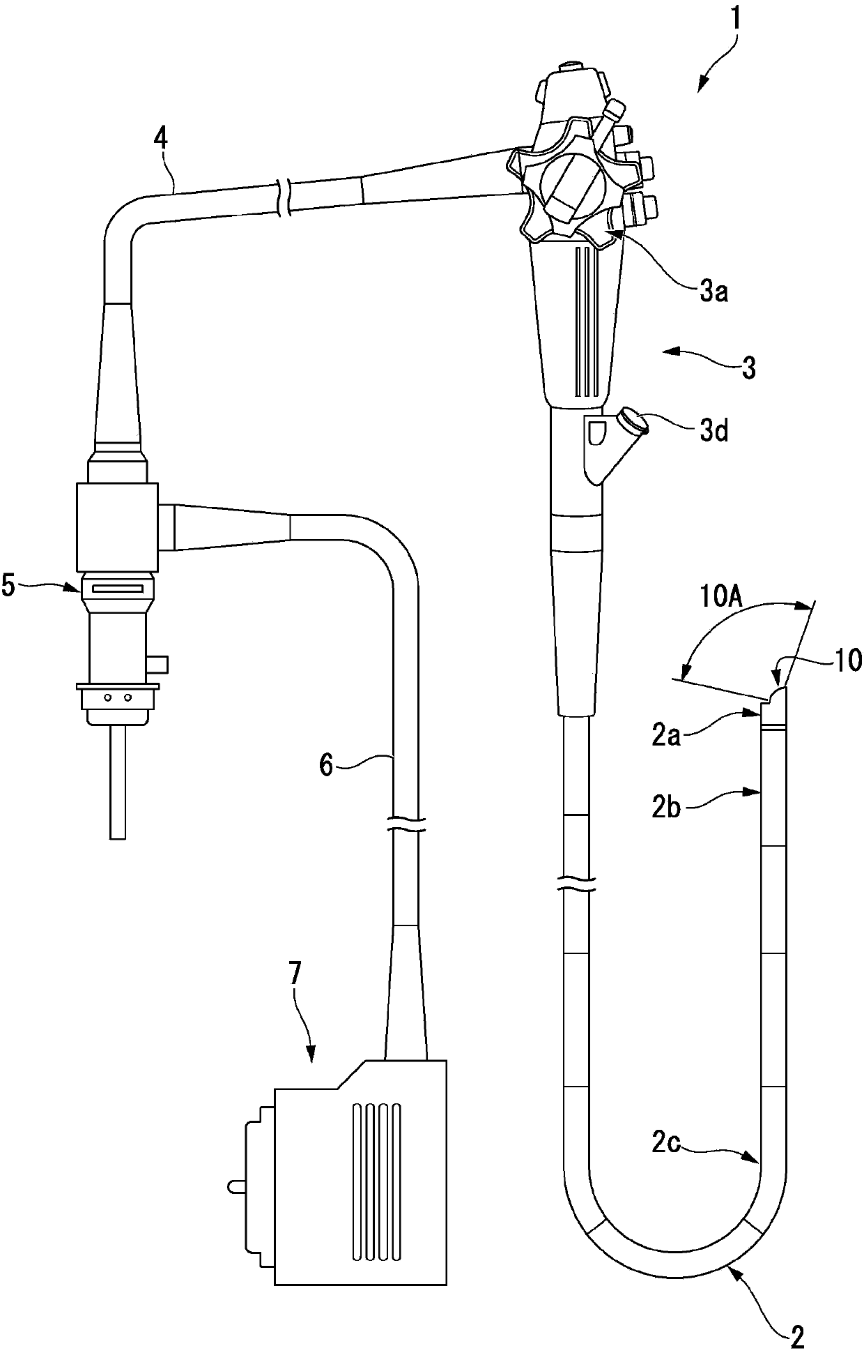
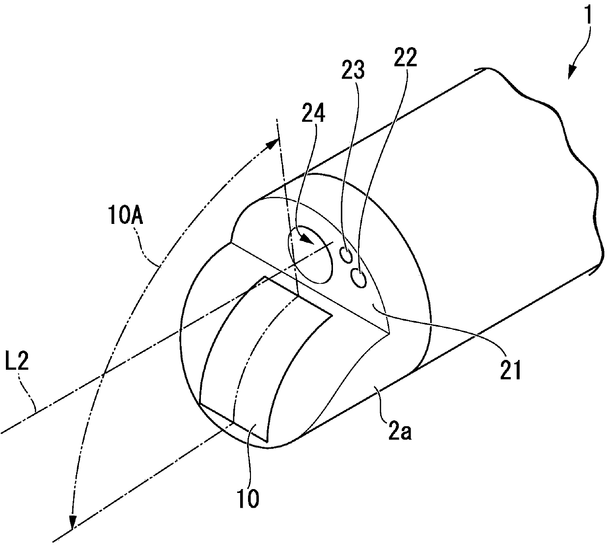
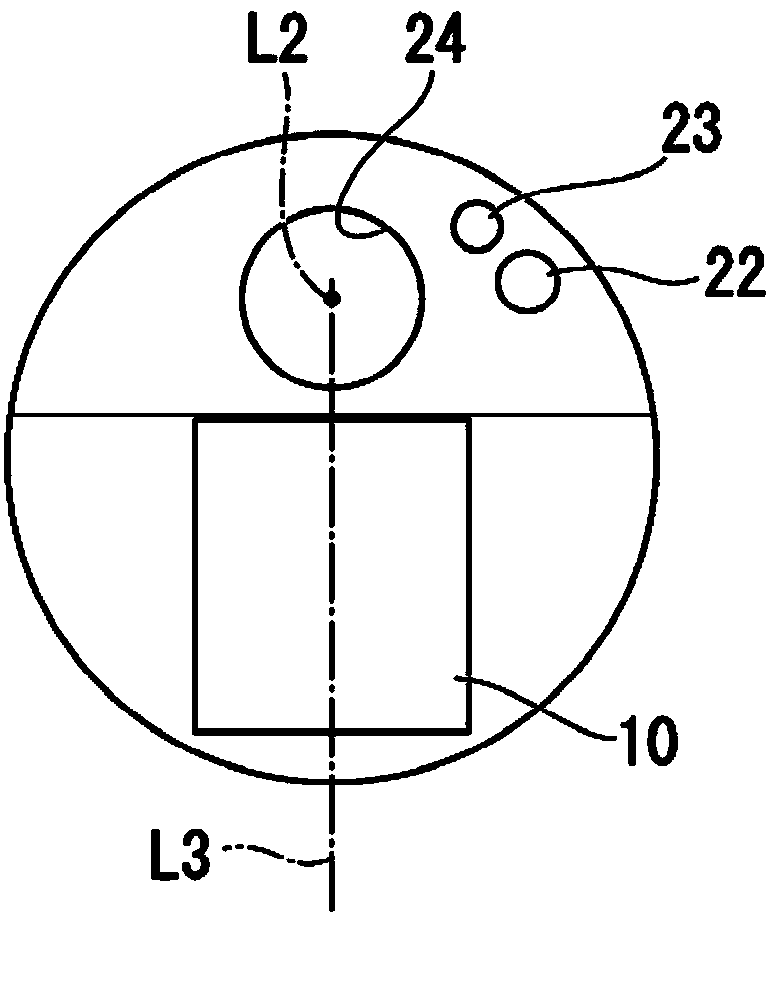
[0067] use Figure 1 ~ Figure 4 The ultrasound endoscope of this embodiment will be described. figure 1 It is a figure which shows the structure of an ultrasonic endoscope. figure 2 It is a perspective view showing the distal end of the ultrasonic endoscope. image 3 is viewed from the front figure 2 The front view when the top part is shown. Figure 4 It is a perspective cross-sectional view of a distal end portion of an ultrasound endoscope.
[0068] An ultrasonic endoscope 1 is configured to include an elongated insertion portion 2 inserted into a body cavity, an operation portion 3 provided at a proximal end of the insertion portion 2 , and a universal cable 4 extending from the side of the operation portion 3 .
[0069] An endoscope connector 5 is provided at the proximal end of the universal cord 4 . An ultrasonic cable 6 extends from the side of the en...
no. 2 approach )
[0122] In the first embodiment, a case where a solid insert is left in the body is described, but instead, a case where a gaseous or liquid drug is injected into the body will be described as a second embodiment. Hereinafter, the parts having the same configuration as those of the first embodiment will be omitted, and only the differences will be described.
[0123] use Figure 19 ~ Figure 20 The ultrasonic puncture needle used in this embodiment will be described. Figure 19 It is the overall appearance diagram of the ultrasonic puncture needle. Figure 20 is an overall sectional view of the ultrasonic puncture needle.
[0124] A syringe 52 is attached to the resin head member 43 . The injection cylinder 52 is composed of a cylinder head 52a, a cylinder body 52b, and a piston 52c, and a gaseous or liquid medicine 53 is contained in the cylinder body 52b.
[0125] The mechanism for controlling the angular position of the needle tube 34 around the axis is the same as that of ...
no. 3 approach )
[0128] A configuration in which the tip shape of the needle tube is different from that of the first and second embodiments will be described as a third embodiment. In addition, in the present embodiment, the substance delivered into the body may be a solid substance such as the insert 35 or a gaseous or liquid medicine 53 or the like. In the ultrasonic puncture needle of the present embodiment, when feeding out solid matter, the structure other than the tip of the needle tube is the same as that of the first embodiment. In addition, in the ultrasonic puncture needle of the present embodiment, when delivering gas or liquid such as the medicine 53 , the structure other than the tip of the needle tube is the same as that of the second embodiment. Here, only the structural differences from the first and second embodiments will be described.
[0129] like Figure 21A ~ Figure 21C As shown, the tip of the needle tube 54 is sharp, and an opening 54a is provided on the side. The d...
PUM
 Abstract
Description
Claims
Application Information
 - R&D Engineer
- R&D Manager
- IP Professional
- Industry Leading Data Capabilities
- Powerful AI technology
- Patent DNA Extraction
Browse by: Latest US Patents, China's latest patents, Technical Efficacy Thesaurus, Application Domain, Technology Topic, Popular Technical Reports.
© 2024 PatSnap. All rights reserved.Legal|Privacy policy|Modern Slavery Act Transparency Statement|Sitemap|About US| Contact US: help@patsnap.com


