
Contactless power transfer device for moving part

一种非接触供电、移动体的技术,应用在电路装置、电池电路装置、控制装置等方向,能够解决损耗轮胎、不能发挥非接触供电变压器、难性能等问题

Inactive Publication Date: 2013-10-30
TECHNOVA +1
View PDF8 Cites 11 Cited by
  • Summary
  • Abstract
  • Description
  • Claims
  • Application Information

AI Technical Summary

Problems solved by technology

[0018] However, for the method of using concrete blocks to limit the left and right positions of the vehicle to guide the power receiving coil into the power supply range, it is difficult to drive, and there is a possibility of tire wear, so it is difficult to apply to ordinary passenger vehicles.
In addition, the method of moving the power receiving transformer up and down complicates the system and leads to an increase in cost
In addition, these methods of mechanically restricting the position are methods of forcing power supply within a narrow allowable range, and cannot take advantage of the advantages of a non-contact power supply transformer that can expand the range of power supply by studying the winding method of the coil, etc.
[0019] In addition, the method of judging the power supply range based on the communication sensitivity between the communication coils provided in the power transmitting coil and the power receiving coil has the following disadvantages, that is, whether to make the vehicle move forward or backward when it is determined that the power supply range is out of the range, or, It is not easy to know the directionality of the correction whether it should be approached to the left or to the right
In addition, the available power supply range is also determined by the size of the transmission range of the communication coil, and it is difficult to make it match the performance of the non-contact power supply device

Method used

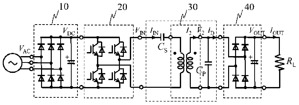
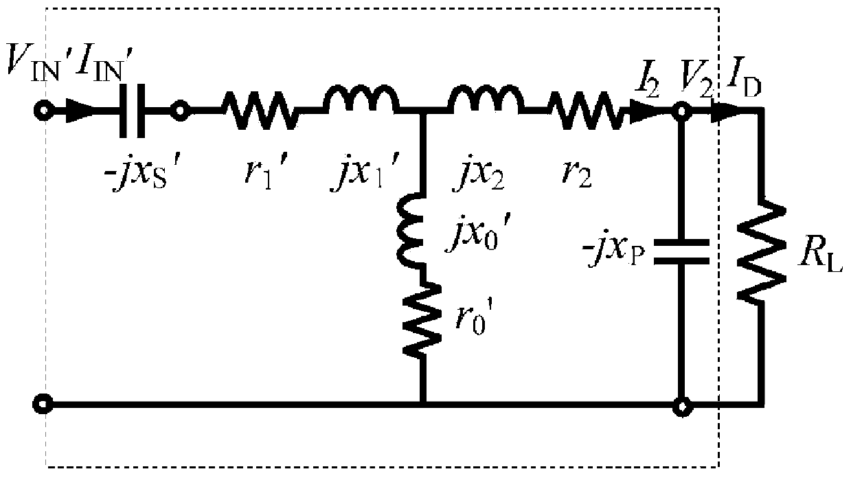

Image

  • Contactless power transfer device for moving part
  • Contactless power transfer device for moving part
  • Contactless power transfer device for moving part

Examples


Embodiment Construction

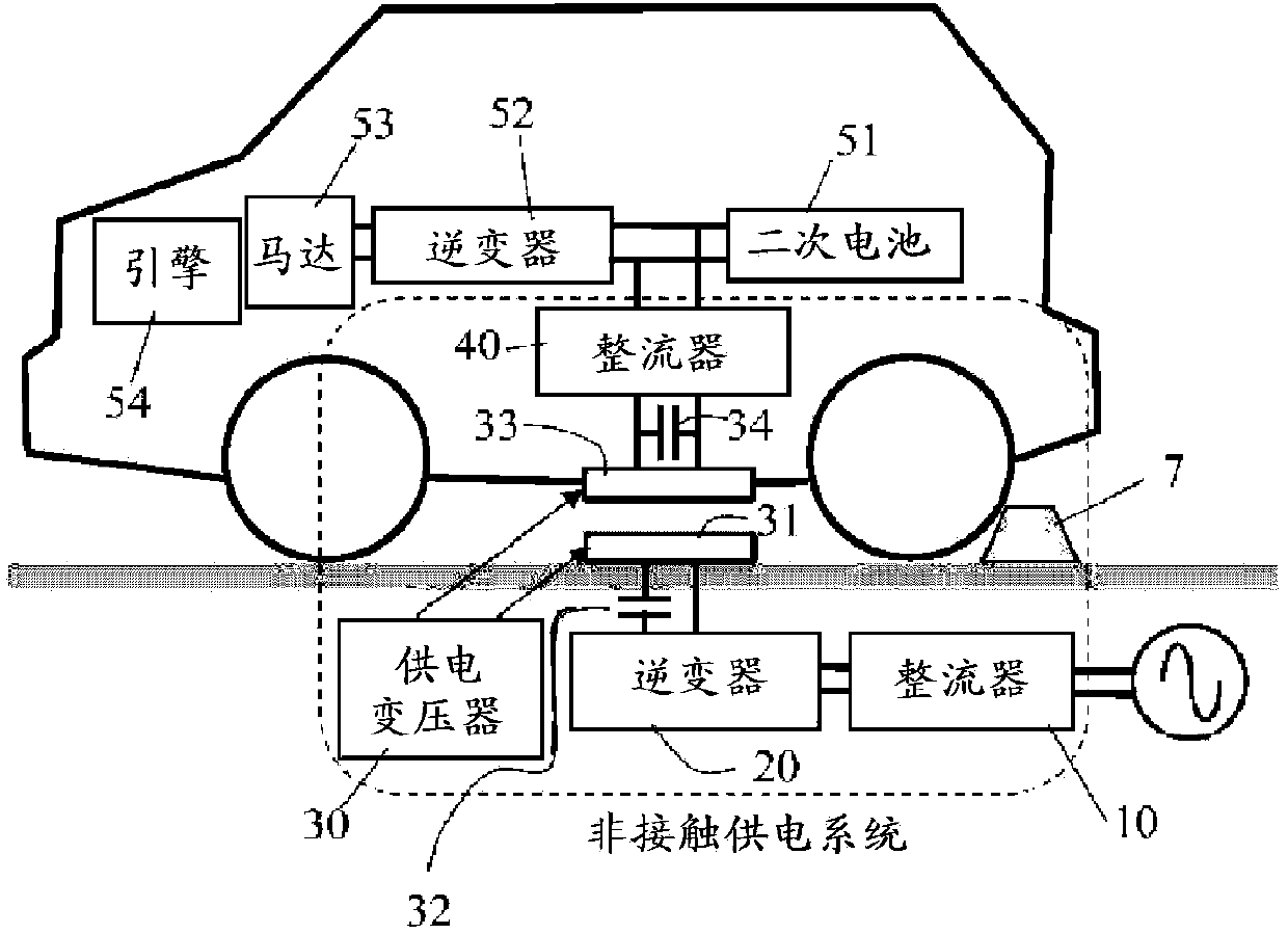
[0063] figure 1 A mode in which the contactless power supply device of the present invention is used for charging a plug-in hybrid vehicle is schematically shown.

[0064] A plug-in hybrid vehicle that receives charging includes an engine 54 and a motor 53 as drive sources, and includes a secondary battery 51 as a power source for the motor, and an inverter that converts the direct current of the secondary battery into alternating current and supplies it to the motor. 52.

[0065] The contactless power supply system that supplies power to the secondary battery 51 includes a rectifier 10 on the ground side that converts the alternating current of a commercial power source into a direct current, an inverter 20 that generates a high-frequency alternating current from the direct current, and a power supply that is one of the contactless power supply transformers 30 . The electric coil 31 and the primary-side series capacitor 32 connected in series to the electric power transmiss...


PUM


Abstract

Provided is a contactless power transfer device for a moving part, and in the contactless power transfer device, it can be simply determined whether a positional deviation between a power transmission coil and a power receiving coil is within an allowable range. Each of the power transmission coil and the power receiving coil comprises an H-shaped core, and search coils (Cy1a, Cy1b, Cy2a, Cy2b, Cx1, and Cx2) are installed on a magnetic pole part of the H-shaped core of the power transmission coil. A y-direction positional deviation between the power transmission coil and the power receiving coil is detected using voltages measured at Cy1a, Cy1b, Cy2a, and Cy2b, and an x-direction positional deviation is detected using voltages measured at Cx1 and Cx2. In addition, the directivity of positional deviation can be checked in the contactless power transfer device.

Description

technical field [0001] The present invention relates to a non-contact power supply device for a mobile body that supplies power to a mobile body such as an electric vehicle in a non-contact manner, and the non-contact power supply device for a mobile body can easily distinguish the positional displacement of the power transmission coil and the power reception coil during power supply Is it within the allowable range. Background technique [0002] The non-contact power supply device includes a non-contact power supply transformer composed of a power transmitting coil (primary coil) and a power receiving coil (secondary coil), and a capacitor connected to the power transmitting coil and the power receiving coil. The electromagnetic induction between them supplies power from the power transmitting coil to the power receiving coil. [0003] A non-contact power supply system including this non-contact power supply device includes: a high-frequency power supply for supplying high...

Claims


Application Information

Patent Timeline
Patent Type & Authority Applications(China)
IPC IPC(8): H02J17/00H02J7/00B60L5/00B60L50/16
CPCH02J7/025H01F38/14B60L11/182H02J5/005Y02T90/14H01F27/28Y02T10/7088Y02T90/122Y02T10/7005B60R16/03Y02T10/7072B60L2210/30B60L2210/40B60L2250/16B60L2270/147B60L2240/622Y02T90/16Y02T10/70Y04S30/14B60L53/22B60L50/16B60L53/65B60L53/122B60L53/126Y02T10/72Y02T90/12Y02T90/167H02J50/80H02J50/12H02J50/70H02J50/90
Inventor 阿部茂保田富夫铃木明
Owner TECHNOVA
Learn More