
Stepped energy dissipation method and energy dissipater through aerification in pre-positioned aerification tanks

An energy dissipation technology, applied in water conservancy projects, sea area engineering, coastline protection, etc., can solve the problems of weakened energy dissipation, structural cavitation damage, etc., achieve simple structure, convenient construction, and overcome easy cavitation Effect

Inactive Publication Date: 2013-11-06
HOHAI UNIV
View PDF6 Cites 5 Cited by
  • Summary
  • Abstract
  • Description
  • Claims
  • Application Information

AI Technical Summary

Problems solved by technology

When the single-width flow rate increases, the water depth on the step surface increases, and the aeration point moves downstream greatly, within a certain range at the beginning of the step, resulting in weakened energy dissipation and severe cavitation damage to the structure

Method used


Image

  • Stepped energy dissipation method and energy dissipater through aerification in pre-positioned aerification tanks
  • Stepped energy dissipation method and energy dissipater through aerification in pre-positioned aerification tanks
  • Stepped energy dissipation method and energy dissipater through aerification in pre-positioned aerification tanks

Examples


Embodiment 1

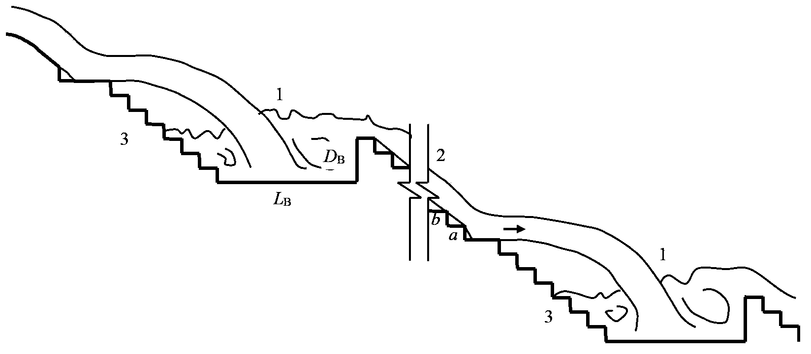
[0030] A step-by-step energy dissipation method for aeration in a pre-aeration pool, for 200m-300m high dam drainage structures, energy dissipation is carried out by stages. Carry out pre-aeration tank aeration and step energy dissipation on the outlet water tongue several times in turn. An aeration vortex is formed in the aeration pool 1 and fully aerated, and then the stepped chute 2 is used to dissipate energy in steps on the fully aerated water flow. In this embodiment, the number of pre-aeration pool aeration and step energy dissipation for the outflow tongue is 2-3 times.

Embodiment 2

[0032] The utility model relates to an energy dissipator for aeration in a pre-aeration pool, and the energy dissipation of 200m-300m high dam drainage structures is completed by classification. It consists of 2-3 levels of energy dissipation sections. In each level of energy dissipation, it includes an aeration tank, a stepped chute, and a pre-step chute connected to the upstream end of the aeration tank. Then, in the next level of energy dissipation, repeat the above structure. In this embodiment, the number of aeration cells is 2-3. The technical solution described in this embodiment can also be expressed as follows, that is: an energy dissipator for aeration in a pre-aeration tank, which is composed of 2-3 energy dissipation sections connected step by step, and the energy dissipation section includes The aeration tank (1), the downstream end of the aeration tank (1) is connected with a stepped discharge chute 2, and the upstream end of the aeration tank 1 is connected wit...

Embodiment 4

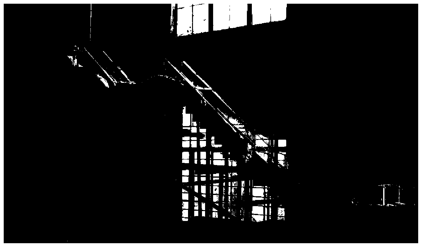
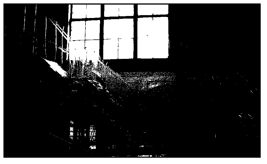
[0039]The test was carried out in the high-speed water flow laboratory of Hohai University. figure 2 It is the photo of the physical model of the test device system and the stepped energy dissipator with aeration in the pre-aeration tank. The test device system includes: water pump motor, water inlet pipe, horizontal water supply tower, model working section, and return water system. The working section of the model is composed of the inlet section of the WES weir and the stepped energy dissipator of the two-stage pre-aeration pool aeration, which is made of plexiglass; the model is designed according to the principle of gravity similarity, and is designed on a scale of 1 / 40 of a certain project. The function of the inlet section is to provide a stable incoming flow and the kinetic energy of the outlet water tongue under the designed single-width flow rate; in the step energy dissipation of each stage of pre-aeration pool aeration, the step horizontal length a=0.09cm, height b...


PUM


Abstract

The invention provides a stepped energy dissipation method and an energy dissipater through aerification in pre-positioned aerification tanks. The method comprises the steps as follows: the aerification in pre-positioned aerification tanks and stepped energy dissipation are sequentially performed on a water outflowing tongue repeatedly to enable the water outflowing tongue to be led into one aerification tank, then the water outflowing tongue forms aerification rotating and rolling in the aerification tank and full aerification is performed, and a stepped discharge chute is utilized to perform stepped energy dissipation on the water flow after full aerification. The energy dissipater comprises the aerification tanks which gradually descend in position and have the same quantity with graded stages, stepped discharge chutes are connected to the back of the aerification tanks, and pre-positioned steps are connected to the upstream ends of the aerification tanks, so that a complete one-stage energy dissipater is formed. Then in the next-stage energy dissipation, the structure is repeated. According to the invention, a higher energy dissipation rate can be kept and cavitation and cavitation erosion damage to the structure can be avoided under large discharge per unit width, and requirements of the engineering on energy dissipation and safety can be met.

Description

technical field [0001] The invention relates to an energy dissipating method and an energy dissipating tool in a discharge structure of a water conservancy and hydropower project, in particular to a stepwise energy dissipating method and a corresponding energy dissipating tool for aeration in a pre-aeration tank. Background technique [0002] In recent years, with the development of water conservancy and hydropower engineering construction, the problem of high-speed water flow in discharge structures of water conservancy and hydropower projects characterized by narrow valleys, high water heads and large discharge volumes is particularly prominent, and the problems of energy dissipation and anti-scour and cavitation cavitation are becoming more and more serious. Attracting attention has always been a difficult and restrictive problem to be solved in engineering design. For example, the Ertan Hydropower Project built in the last century has a dam height of 240m and a discharge...

Claims


Application Information

Patent Timeline
IPC IPC(8): E02B8/06
Inventor 钱尚拓吴建华马飞李书芳姚莉樊博王宇
Owner HOHAI UNIV
Learn More