Dot-matrix type heat conduction temperature measurement nondestructive crack detection method

A crack detection and heat conduction technology, applied in the direction of optical testing flaws/defects, etc., can solve the problems of difficult and accurate detection of superficial micro-cracks, and achieve the effect of simple and intuitive detection methods and intuitive and accurate detection results.

Inactive Publication Date: 2013-11-06
HARBIN INST OF TECH
View PDF6 Cites 17 Cited by
  • Summary
  • Abstract
  • Description
  • Claims
  • Application Information

AI Technical Summary

Problems solved by technology

[0019] In view of the defect that the existing surface detection crack technology is difficult to accurately detect superficial micro-cracks, the present invention provides a non-destructive crack detection method of lattice heat conduction temperature measurement

Method used


Image

  • Dot-matrix type heat conduction temperature measurement nondestructive crack detection method
  • Dot-matrix type heat conduction temperature measurement nondestructive crack detection method
  • Dot-matrix type heat conduction temperature measurement nondestructive crack detection method

Examples


specific Embodiment approach 1

[0036] Specific embodiment one: the non-destructive crack detection method of lattice heat conduction temperature measurement of the present embodiment comprises the following steps:

[0037] (1) Divide the entire surface of the workpiece to be measured into n lattices to be measured according to the X-Y coordinates.

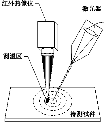
[0038] (2) Set up a laser and an infrared thermal imager above the dot matrix to be measured, irradiate the laser beam with the set power on the surface of the workpiece to be tested, and use the infrared thermal imager to detect the surface of the workpiece to be tested at a distance of 1-10mm from the laser spot in real time The temperature rise curve, detect its highest value.

[0039] The material and surface roughness of the workpiece affect the absorption rate of the laser. The key to this detection method is to rapidly increase the temperature of the irradiation point of the workpiece by tens of degrees to one or two hundred degrees, that is, the gen...

specific Embodiment approach 2

[0046] Specific implementation mode two: the non-destructive crack detection method of lattice heat conduction temperature measurement of the present embodiment comprises the following steps:

[0047] Such as figure 1 As shown, a laser and an infrared thermal imager are installed above the test piece; a beam of laser with a set power is irradiated on the test piece for t1 seconds; at the same time, an infrared thermal imager is used to detect a laser spot at a distance of L=1mm. Set the temperature rise curve of the temperature measurement area (generally within a few square mm, and keep the L distance and the area of ​​the set area unchanged) during the entire detection process, and detect the highest value.

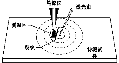
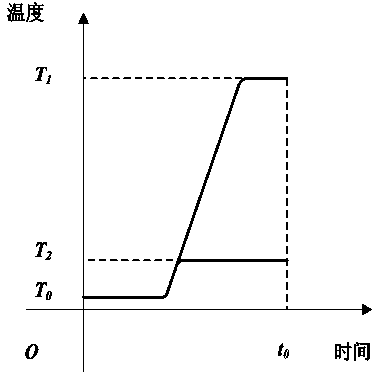
[0048] When there is no crack between the laser spot and the detection area, the heat conduction is good, and the temperature rise is very high; when there is a crack between the laser spot and the detection area, the maximum value of the measured temperature rise is lo...


PUM


Abstract

Relating to a crack detection method, the invention provides a dot-matrix type heat conduction temperature measurement nondestructive crack detection method. The method includes the steps of: disposing a laser and an infrared thermal imager over a to-be-detected workpiece, making a laser beam irradiate the surface of the to-be-detected workpiece at set power, simultaneously using the infrared thermal imager to detect a surface temperature rise curve of the to-be-detected workpiece at a position of 1-10mm distant from a laser spot in real time, detecting a maximum value, and comparing the temperature rise maximum value to judge whether a crack defect exists at the position on the to-be-detected workpiece surface. The whole workpiece surface is divided into n to-be-detected dot matrixes according to X-Y coordinates. After point-by-point detection, the recorded abnormal low temperature point coordinates are drawn into a graph, so that the position and shape of the crack on the to-be-detected workpiece can be known intuitively. With wide application, the method not only has a high detection rate on a superficial microcrack on the workpiece, and also can trace out its position, shape, depth and other three-dimensional information. Being simple and visible, the detection process needs no intermediate medium, has no adverse effect on the workpiece, and the detection result is visible and accurate.

Description

technical field [0001] The invention relates to a crack detection method, in particular to a non-destructive crack detection method. Background technique [0002] The most serious defect in machine parts is the appearance of cracks. There are various reasons for cracks, mainly as follows: [0003] First, cracks arising from raw materials during the manufacturing phase; [0004] Second, the cracks generated in the processing and manufacturing stage; [0005] Third, the cracks that occur in the equipment during use. [0006] These cracks are usually detected using non-destructive testing methods, however, it is difficult to determine whether these cracks are harmful or not. Once a missed judgment occurs, the expansion of cracks on the running parts will cause a great threat and serious consequences to the safe operation of production. [0007] The existing surface detection crack technology mainly has the following methods: [0008] 1. Infiltration method: [0009] Pene...

Claims


Application Information

Patent Timeline
Patent Type & Authority Applications(China)
IPC IPC(8): G01N21/88
Inventor 孔令超张威田艳红王春青李海龙
Owner HARBIN INST OF TECH
Why Eureka
Try Eureka