Plasma arc method for perforating key hole by current

A plasma arc and plasma arc technology, applied in plasma welding equipment, manufacturing tools, welding equipment, etc., can solve problems such as affecting welding and cutting quality, limiting plasma arc efficiency, etc., to increase thickness, improve incision quality, and improve utilization. Effect

Active Publication Date: 2015-05-20
HARBIN INST OF TECH
View PDF6 Cites 0 Cited by
  • Summary
  • Abstract
  • Description
  • Claims
  • Application Information

AI Technical Summary

Problems solved by technology

[0006] The present invention aims to solve the problem that the traditional plasma arc limits the efficiency of the plasma arc and affects its welding and cutting quality due to the existence of inherent characteristics, and provides a plasma arc method in which the current runs through the keyhole

Method used


Image

  • Plasma arc method for perforating key hole by current
  • Plasma arc method for perforating key hole by current
  • Plasma arc method for perforating key hole by current

Examples


specific Embodiment approach 1

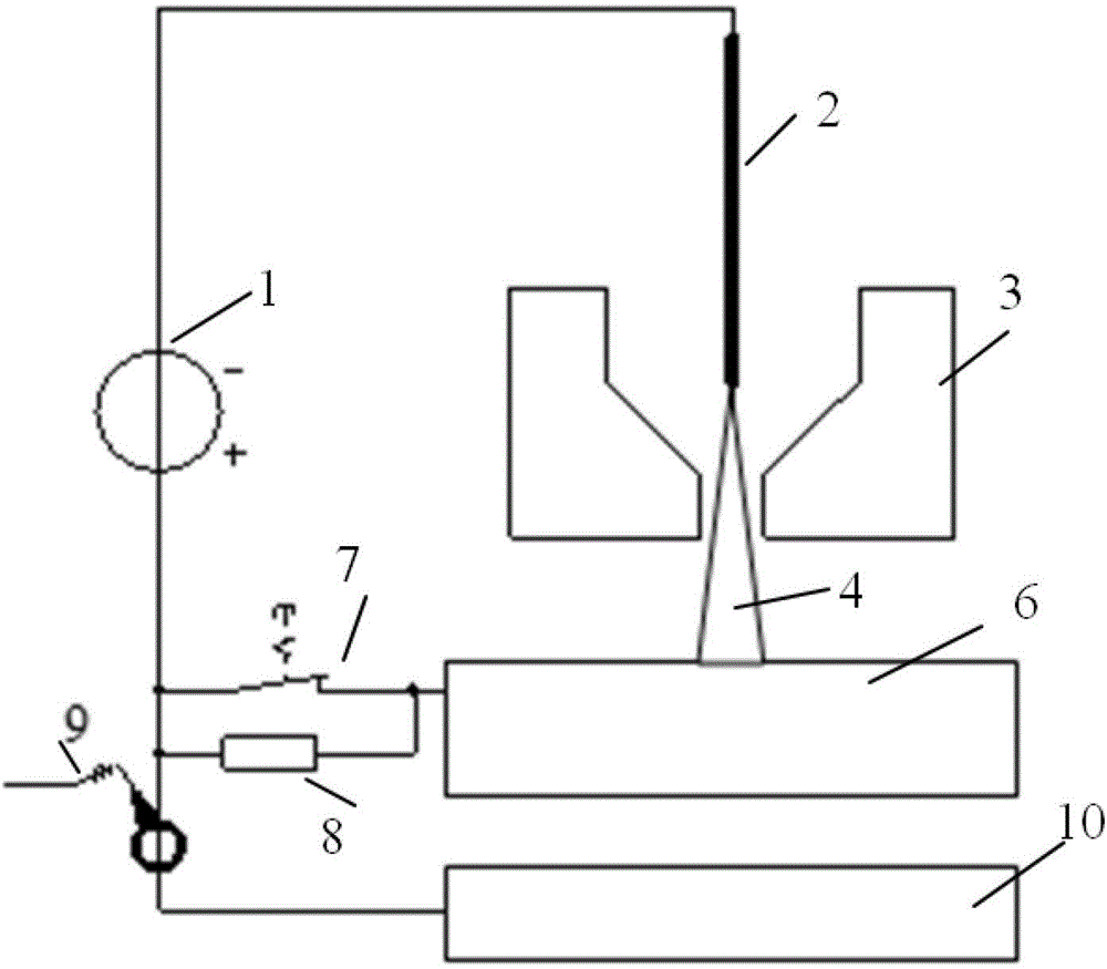
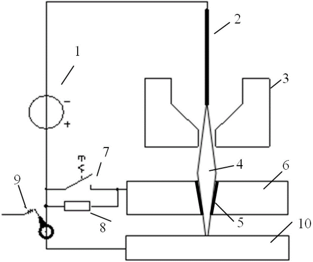
[0017] Specific implementation mode one: the following combination figure 1 and figure 2 Describe the present embodiment, the plasma arc method that the electric current of present embodiment runs through the keyhole, it connects the negative pole of plasma arc power supply 1 to the head end of plasma gun electrode 2, and the end of plasma gun electrode 2 corresponds to plasma gun compression nozzle 3, Connect the positive pole of the plasma arc power supply 1 to the workpiece 6 through the switch 7, the switch 7 is connected in parallel with the current regulator 8, the positive pole of the plasma arc power supply 1 is connected to one end of the current sensor 9 at the same time, and the other end of the current sensor 9 is connected to one end of the receiving electrode 10 , the receiving electrode 10 is placed correspondingly to the workpiece 6, and the plasma arc method is:

[0018] Put the switch 7 in the closed state, and put the outlet of the plasma gun compression ...

specific Embodiment approach 2

[0024] Specific implementation mode two: the following combination figure 1 and figure 2 This embodiment will be described. This embodiment will further describe the first embodiment. The current sensor 9 in this embodiment is a through current detector.

specific Embodiment approach 3

[0025] Embodiment 3: This embodiment further describes Embodiment 1 or 2. The receiving electrode 10 in this embodiment is a metal plate, a metal rod or a metal electrode.

[0026] In this embodiment, the receiving electrode 10 is a metal plate parallel to the workpiece 6 in most cases; it can also be simplified as a metal rod parallel to the workpiece 6 in some cases, such as for welding or cutting of only a single straight line; or It can also be simplified as a metal electrode perpendicular to the workpiece 6 and corresponding to the position of the plasma gun electrode 2 , for example, when the workpiece 6 can move or the receiving electrode 10 can move synchronously with the plasma gun electrode 2 . The receiving electrode 10 can be water-cooled to withstand large currents as required.


PUM


Abstract

The invention discloses a plasma arc method for perforating a key hole by current and belongs to the technical field of thermal processing. The problems that plasma arc efficiency is limited and welding quality and cutting quality are affected due to inherent characteristics of traditional plasma arc are solved. An outlet of a plasma gun compression nozzle is close to a to-be-processed part of a workpiece, so that under the action of a plasma arc power supply, a plasma arc is formed between the tail end of the electrode of a plasma gun and the to-be-processed part of the workpiece; the plasma arc and the plasma arc power supply form a first plasma current loop through the workpiece and a switch; meanwhile, when current is monitored to exist in a current sensor, the switch is turned off, the plasma arc penetrates through the key hole and forms a second plasma current loop with an accepting electrode and the plasma arc power supply; and meanwhile, the plasma arc and the plasma arc power supply form a pilot arc passage through the workpiece and a current regulator. Therefore, the current of the plasma arc can penetrate through the key hole. The method is used for forming the plasma arc.

Description

technical field [0001] The invention relates to a plasma arc method for current passing through a keyhole, and belongs to the technical field of thermal processing. Background technique [0002] Plasma arc is a high-energy beam heat source with energy density second only to laser, which is widely used in thermal processing technology fields such as welding and cutting. [0003] Whether the existing plasma arc is used in welding or cutting technology, its basic working principle is the same, and its basic working principle is: image 3 As shown, the plasma arc power supply 1 forms a closed circuit through the plasma gun electrode 2, the plasma gun compression nozzle 3, the plasma arc 4 and the keyhole 5 on the workpiece 6, wherein the keyhole 5 is the thermal force of the plasma arc 4 acting on the workpiece 6 A small hole formed is an important technical feature of high-energy beam heat source in welding or cutting technology, and the technical feature of keyhole exists in t...

Claims


Application Information

Patent Timeline
Patent Type & Authority Patents(China)
IPC IPC(8): B23K10/00H05H1/34
Inventor 耿正
Owner HARBIN INST OF TECH
Why Eureka
Try Eureka