Eureka AIR delivers breakthrough ideas for toughest innovation challenges, trusted by R&D personnel around the world.

Self-rheostat-starting wound rotor electric motor device

A wound rotor and motor technology, applied in electromechanical devices, asynchronous induction motors, starters of a single DC motor, etc., can solve problems such as needs, and achieve the effect of good integration and high reliability

Active Publication Date: 2013-11-13
镇江泽佳汽车零部件有限公司
View PDF4 Cites 0 Cited by
  • Summary
  • Abstract
  • Description
  • Claims
  • Application Information

AI Technical Summary

Problems solved by technology

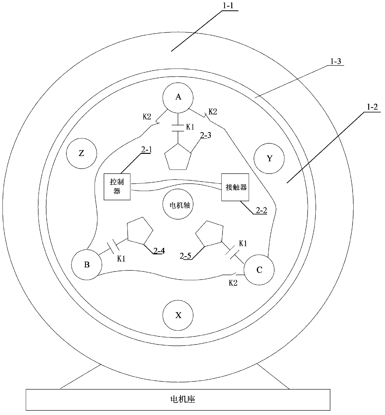
[0003] The purpose of the present invention is to solve the problem that the existing rotor winding external resistance technology requires brushes and slip ring mechanisms, and needs to control the connection and disconnection of the resistance, and provides a motor device for starting a wound rotor with a self-varistor

Method used


Image

  • Self-rheostat-starting wound rotor electric motor device
  • Self-rheostat-starting wound rotor electric motor device
  • Self-rheostat-starting wound rotor electric motor device

Examples


specific Embodiment approach 1

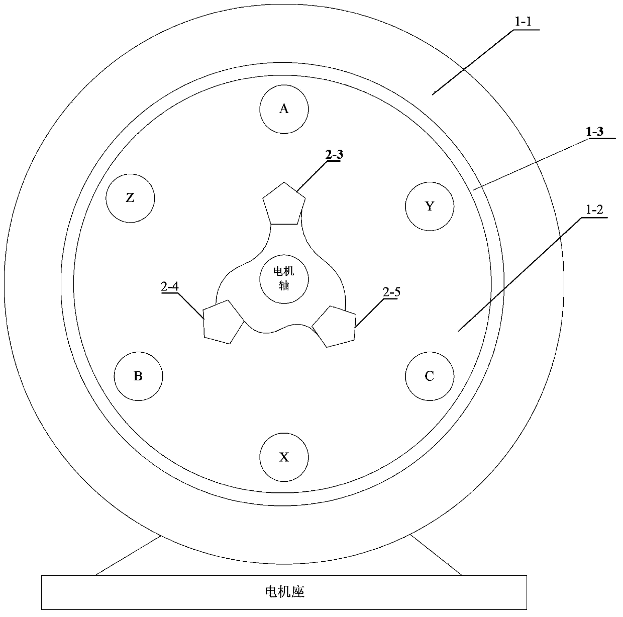
[0008] Specific implementation mode one: combine figure 1 , figure 2 , image 3 with Figure 4 Describe this embodiment, the motor device for starting a wound rotor from a variable resistance described in this embodiment, it includes a wound rotor motor 1, the rotor core 1-2 is coaxially set in the inner cavity of the stator 1-1, and the rotor There is an air gap 1-3 between the outer surface of the iron core 1-2 and the inner surface of the stator 1-1, and the three-phase windings are correspondingly wound around the outer surface of the rotor iron core 1-2, and the three-phase windings are respectively AX and BY And CZ, it also includes controller 2-1, contactor 2-2, No. 1 resistor 2-3, No. 2 resistor 2-4, No. 3 resistor 2-5 and generator speed sensor S, controller 2-1, contactor 2-2, No. 1 resistor 2-3, No. 2 resistor 2-4, No. 3 resistor 2-5 and generator speed sensor S are all placed in the inner cavity of rotor core 1-2 Among them, one end of the No. 1 resistor 2-3 i...

specific Embodiment approach 2

[0013] Specific embodiment 2: This embodiment is a further limitation of the motor device for starting the wound rotor from the rheostat described in specific embodiment 1. The generator speed measuring sensor S adopts a ZCF121 sensor.

specific Embodiment approach 3

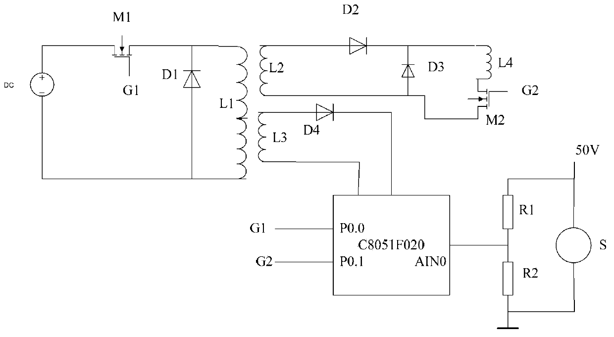
[0014] Specific implementation mode three: combination image 3 This embodiment is described. This embodiment is a further limitation of the motor device for starting a wound rotor with a self-varistor described in Embodiment 1. The controller 2-1 adopts a C8051F020 single-chip microcomputer.

[0015] For the block diagram of the control flow of the single-chip microcomputer, see Figure 4 .


PUM


Abstract

The invention provides a self-rheostat-starting wound rotor electric motor device, relates to starting electric motors and aims at solving the problems that an electric brush and a slip ring mechanism are needed and control of the connection and the disconnection of resistors needs to be performed in an existing rotor winding externally-connected technique. The self-rheostat-starting wound rotor electric motor device comprises a controller, a contactor, a first resistor, a second resistor, a third resistor and a generator speed measuring sensor; the controller, the contactor, the first resistor, the second resistor, the third resistor and the generator speed measuring sensor are all arranged in an inner cavity of a rotor iron core, the first resistor is communicated with the A end of an AX winding, the second resistor is communicated with the B end of a BY winding, the third resistor is communicated with the C end of a CZ winding, the A end, the B end and the C end are connected onto a normally-closed contact of the contactor simultaneously, and the winding of the contactor is correspondingly communicated with the controller; the signal output end of the generator speed measuring sensor is communicated with the input end of speed measurement signals of the controller.

Description

technical field [0001] The invention relates to a starter motor arrangement. Background technique [0002] Current wound rotor motors lead out the rotor windings through a brush and slip ring system. In order to start with a larger starting torque, the rotor winding is generally connected in series with a resistor when starting, and the resistor is removed after the start is completed, and a frequency-sensitive resistor can also be connected in series according to this principle. However, the rotor winding external resistor technology requires a brush and slip ring mechanism, and needs to control the connection and disconnection of the resistance. Contents of the invention [0003] The purpose of the present invention is to solve the problem that the existing rotor winding external resistance technology requires brushes and slip ring mechanisms, and needs to control the connection and disconnection of the resistance, and provides a motor device for starting a wound rotor ...

Claims


Application Information

Patent Timeline
Patent Type & Authority Applications(China)
IPC IPC(8): H02K17/30H02P1/20
Inventor 王丁张廷宇
Owner 镇江泽佳汽车零部件有限公司
Why Eureka
Eureka Blog
Learn More