High-performance charge pump circuit in low-voltage charge pump phase-locked loop

A technology of charge pump and phase-locked loop, which is applied in the direction of conversion equipment without intermediate conversion to AC, can solve the problems of differences in the locking time of the phase-locked loop and affect the phase noise performance of the phase-locked loop, and achieve the expansion of the output voltage range, The effect of overcoming the narrow output voltage range and good stability performance

Active Publication Date: 2013-11-13
杭州中科微电子有限公司
View PDF6 Cites 8 Cited by
  • Summary
  • Abstract
  • Description
  • Claims
  • Application Information

AI Technical Summary

Problems solved by technology

However, using an operational amplifier but in the entire matching range, due to the 65nm and below technology, the channel modulation effect of the transistor is very obvious. Under different output voltages Vctrl, the charge and discharge currents are different, and the charging and discharging current of the loop filter is different. The discharge time is different, so that the locking time of the phase-locked loop is different under different voltage control voltages, which will affect the phase noise performance of the phase-locked loop

Method used


Image

  • High-performance charge pump circuit in low-voltage charge pump phase-locked loop
  • High-performance charge pump circuit in low-voltage charge pump phase-locked loop
  • High-performance charge pump circuit in low-voltage charge pump phase-locked loop

Examples


Embodiment Construction

[0039] The present invention will be further described below in conjunction with specific drawings and embodiments.

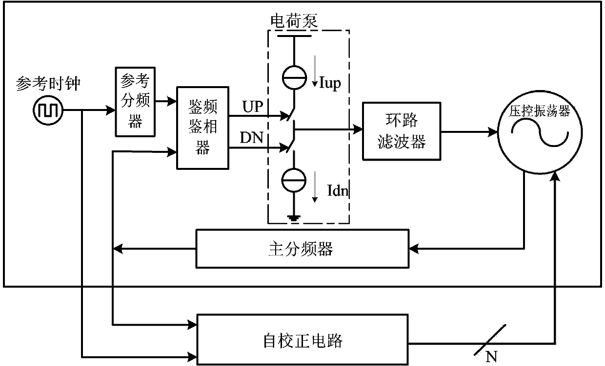
[0040] Such as figure 1 As shown: the charge pump is connected after the frequency and phase detector, and before the loop filter and the voltage-controlled oscillator. The performance of the charge pump directly affects the performance of the voltage-controlled oscillator, and then affects the performance of the phase-locked loop. It is a very critical circuit module in the phase-locked loop structure.

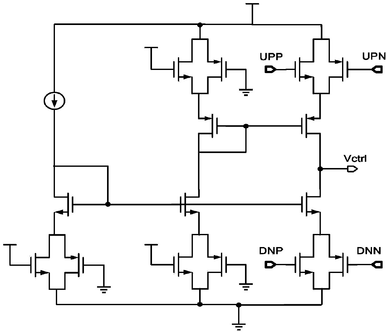
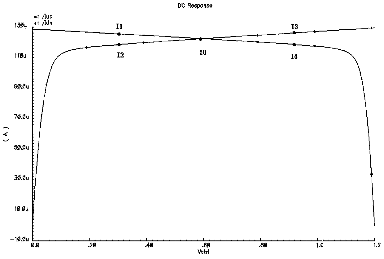
[0041] Such as figure 2 As shown, it is a traditional charge pump circuit, and the corresponding quiescent current matching result of this circuit is shown in image 3 As shown, the matching range that can meet the requirements is very small, which can hardly meet the basic use. The channel modulation effect of transistors in the 65nm and below processes is very obvious, and the working voltage is further reduced in the sub-micron process. It is impossible...


PUM


Abstract

The invention relates to a high-performance charge pump circuit in a low-voltage charge pump phase-locked loop. The high-performance charge pump circuit comprises a charge-discharge circuit and a current duplicate circuit, wherein a first current duplicate branch circuit, a second current reproduce branch circuit, a first charge-discharge branch circuit and a second charge-discharge branch circuit are connected with a bias circuit; the second current duplicate branch circuit and the first charge-discharge branch circuit are connected with a first rail-to-rail operational amplifier; the first current duplicate branch circuit and the second charge-discharge branch circuit are connected with a second rail-to-rail operational amplifier; an output end of the first rail-to-rail operational amplifier is connected with a non-inverting input end through a first Miller compensating circuit; an output end of the second rail-to-rail operational amplifier is connected with a non-inverting input end through a second Miller compensating circuit; and the current ratio of the second charge-discharge branch circuit to the first current duplicate branch circuit and the current ratio of the first charge-discharge branch circuit and the second current duplicate branch circuit are equal. According to the high-performance charge pump circuit in the low-voltage charge pump phase-locked loop, the current matching range can be expanded, the dynamic current matching performance is good, the stability is high, and the circuit is safe and reliable.

Description

technical field [0001] The invention relates to a circuit structure, in particular to a high-performance charge pump circuit in a phase-locked loop of a low-voltage charge pump, which belongs to the technical field of integrated circuits. Background technique [0002] The charge pump phase-locked loop is the most commonly used phase-locked loop structure in the RF phase-locked loop, such as figure 1 Shown is the current commonly used charge pump phase-locked loop structure, various non-ideal effects will be superimposed together and will deteriorate the characteristics of the phase-locked loop. The role of the charge pump (CP) in the phase-locked loop is to convert the digital control signal (UP, DN) output by the phase-frequency detector (PFD) into a control voltage-controlled oscillator ( VCO) analog control signal. The charge pump plays a decisive role in the performance of the phase-locked loop in the loop: the mismatch of the charge and discharge current of the charge...

Claims


Application Information

Patent Timeline
Patent Type & Authority Applications(China)
IPC IPC(8): H02M3/07
Inventor 罗彦彬甘业兵钱敏陈妙萍马成炎
Owner 杭州中科微电子有限公司
Why Eureka
Try Eureka