
Switching power supply driving chip and switching power supply driving circuit

A switching power supply and driving chip technology, applied in electrical components, adjusting electrical variables, instruments, etc., can solve the problems of many peripheral circuit devices, low working reliability, and large occupied area of ​​the switching power supply driving chip, so as to reduce the board area. The effect of occupying area, improving reliability, and reducing peripheral circuit components

Active Publication Date: 2013-11-13
SHENZHEN SUNMOON MICROELECTRONICS
View PDF6 Cites 23 Cited by
  • Summary
  • Abstract
  • Description
  • Claims
  • Application Information

AI Technical Summary

Problems solved by technology

[0005] The purpose of the embodiment of the present invention is to provide a switching power supply driving circuit, aiming to solve the problem that the existing primary side feedback flyback switching power supply driving circuit uses the auxiliary winding of the transformer to realize the detection of the degaussing signal, so that the periphery of the switching power supply driving chip The problems of many circuit components, high cost, large occupied area, and low working reliability

Method used


Image

  • Switching power supply driving chip and switching power supply driving circuit
  • Switching power supply driving chip and switching power supply driving circuit
  • Switching power supply driving chip and switching power supply driving circuit

Examples


Embodiment Construction

[0025] In order to make the object, technical solution and advantages of the present invention clearer, the present invention will be further described in detail below in conjunction with the accompanying drawings and embodiments. It should be understood that the specific embodiments described here are only used to explain the present invention, not to limit the present invention.

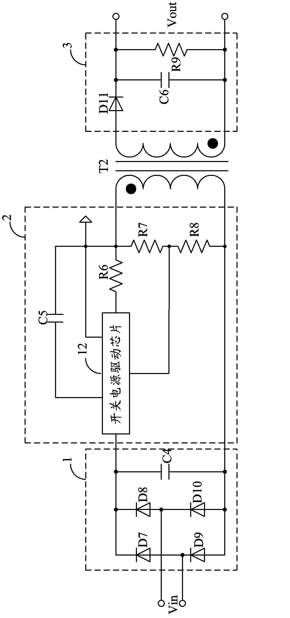
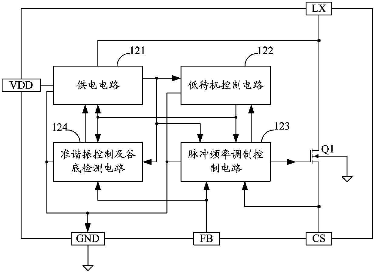
[0026] Aiming at the problems existing in the prior art, the present invention proposes a switching power supply driving chip and a switching power supply driving circuit. The chip uses the quasi-resonance control and valley detection circuit to detect the valley bottom of the transformer in the quasi-resonant state after degaussing. The power supply circuit determines whether to pass through the power tube drain of the chip according to the detected valley bottom and the current voltage value of the power supply pin VDD of the chip. The pin LX supplies power to the power supply pin VDD, and at the...


PUM


Abstract

The invention belongs to the field of switching power supply driving circuits, and provides a switching power supply driving chip and a switching power supply driving circuit, wherein the chip is controlled by quasi-resonance and the valley bottom under the quasi-resonance state is detected by a valley bottom detecting circuit after the transformer is demagnetized, a power supply circuit judges whether to supply power to a power supply pin through a power tube drain electrode of the chip according to the detected valley bottom and the current voltage value of the power supply pin of the chip, and at the same time, a pulse frequency modulation control circuit adjusts the switching frequency of a power tube in the chip according to the value of a feedback pin and a current detection pin of the chip to achieve the constant voltage or constant current output of the switching power supply drive circuit. The switching power supply drive circuit of the chip is adopted, and an auxiliary winding is not required, so that the number of the peripheral circuit devices of the switching power supply drive chip decreases, the cost of the switching power supply drive circuit is lowered, the integration is improved, the board area is reduced, the system operation reliability is improved, and the electricity taking dynamic adjustment is achieved.

Description

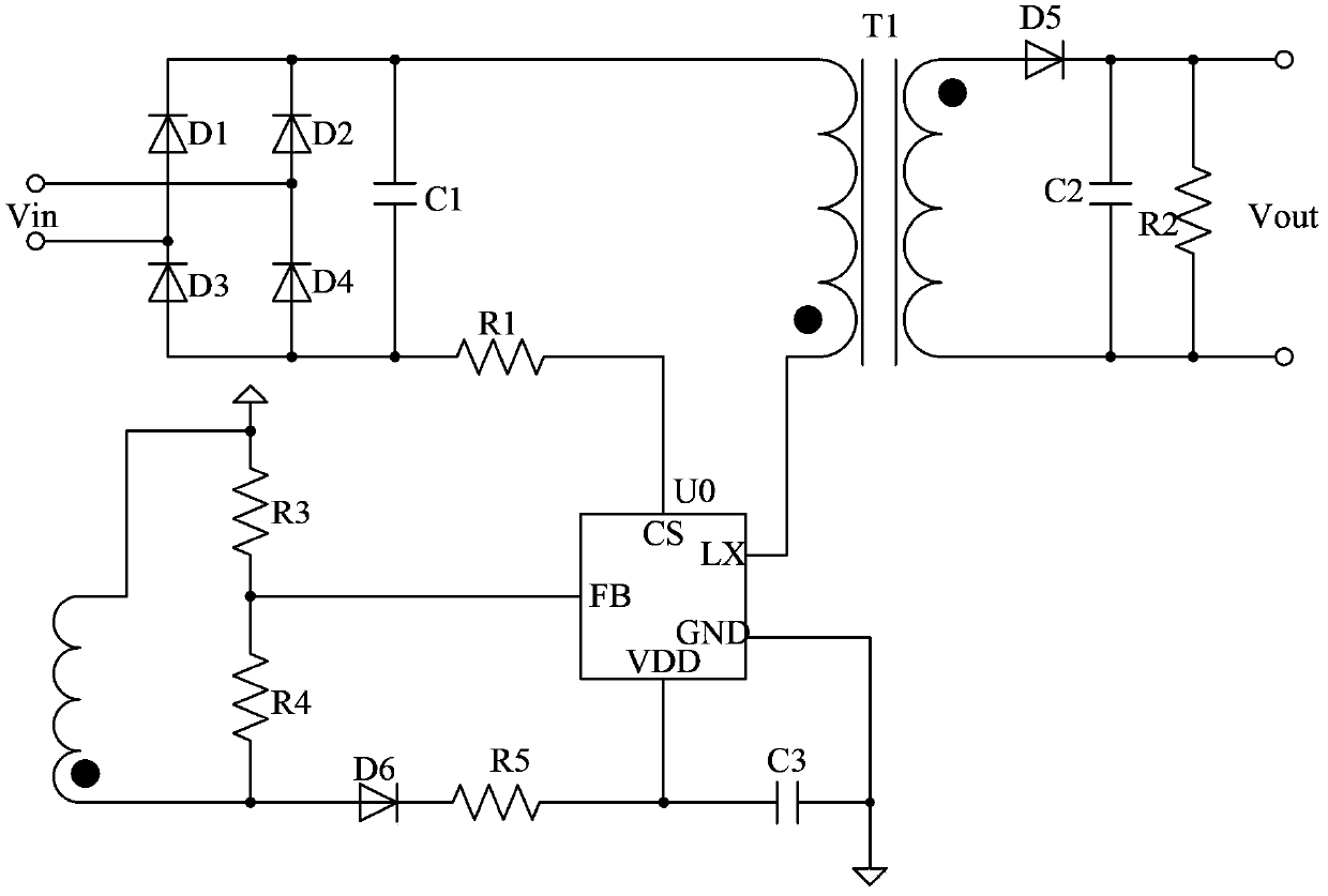
technical field [0001] The invention belongs to the field of switching power supply driving circuit design, in particular to a switching power supply driving chip and a switching power supply driving circuit. Background technique [0002] In the primary side feedback flyback switching power supply drive circuit, the feedback signal of the primary side winding of the transformer is used to realize the control of the output. Such as figure 1 A typical structure of a primary-side feedback flyback switching power supply drive circuit provided by the prior art is shown. [0003] Among them, the diode D1, the diode D2, the diode D3 and the diode D4 form a rectifier bridge, and the rectifier bridge and the capacitor C1 together form an input circuit for rectifying and filtering the AC input voltage Vin and outputting it to the primary winding of the transformer T1 ; Wherein, the diode D5, the capacitor C2 and the resistor R2 form an output circuit, which is used to rectify and fi...

Claims


Application Information

Patent Timeline
Patent Type & Authority Applications(China)
IPC IPC(8): H02M3/335
CPCH02M3/33523H02M1/0006
Inventor 谢靖李照华林道明陈艳霞王文荣
Owner SHENZHEN SUNMOON MICROELECTRONICS
Learn More