A topology of a power converter and its control method

A technology of power converter and topology, applied in the field of non-isolated photovoltaic grid-connected inverter circuit and its control

Inactive Publication Date: 2015-09-30
GIANT IND TECH CO LTD
View PDF2 Cites 0 Cited by
  • Summary
  • Abstract
  • Description
  • Claims
  • Application Information

AI Technical Summary

Problems solved by technology

[0005] In view of the above-mentioned defects in the prior art, the present invention proposes a topology structure of a power converter and its control method, in order to solve the problems of suppressing the above-mentioned common-mode leakage current, reducing the conduction loss of the power switching device and effectively suppressing EMI

Method used


Image

  • A topology of a power converter and its control method
  • A topology of a power converter and its control method
  • A topology of a power converter and its control method

Examples


Embodiment Construction

[0030] In the following, the specific implementation manners of the present invention will be further described in detail in conjunction with the accompanying drawings of the embodiments, so as to make the technical solution of the present invention easier to understand and grasp.

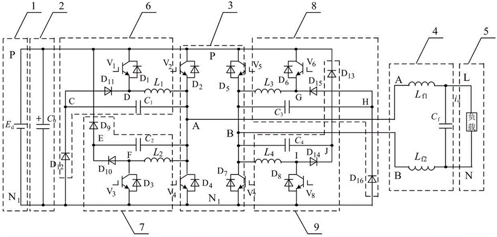
[0031] One, the topological structure of the power converter of the present invention such as figure 1 As shown, its basic composition includes a DC voltage source E d 1. Capacitance C 0 2, by the power switching device V 2 and diode D 2 , power switching device V 4 and diode D 4 , power switching device V 5 and diode D 5 , power switching device V 7 and diode D 7 Composed of inverter unit 3, the inductor L f1 , L f2 , capacitance C f Composed of filtering unit 4 and load 5, where the DC voltage source E d The positive electrode and C 0 positive pole of V 2 collector, D 2 the cathode, V 5 collector, D 5 The cathode of the node is connected to the node P, and the DC voltage source E...


PUM


Abstract

The invention provides a topological structure of an electric power convertor and a control method of the topological structure. Basic components of the topological structure comprise a DC voltage source Ed, a capacitor C0, an inverting unit, a filtering unit and a load; and particularly, on the basis of the basic components, the topological structure is further provided with a main circuit consisting of a first unit, a second unit, a third unit and a fourth unit, wherein the first unit comprises a power switching device V1, a diode D1, an inductor L1, a capacitor C1, a diode D11 and a diode D12, the second unit comprises a power switching device V3, a diode D3, an inductor L2, a capacitor C2, a diode D10 and a diode D9, the third unit comprises a power switching device V6, a diode D6, an inductor L3, a capacitor C3, a diode D15 and a diode D16, the fourth unit comprises a power switching device V8, a diode D8, an inductor L4, a capacitor C4, a diode D14 and a diode D13, and the topological structure is matched with a corresponding control signal for implementation. With the application of the topological structure of the electric power convertor, common mode current and electromagnetic interference of equipment can be obviously restrained, and the conversion efficiency of a device is improved.

Description

technical field [0001] The invention relates to a topology structure of a power converter, in particular to a non-isolated photovoltaic grid-connected inverter circuit and a control method thereof, which can be used for photovoltaic grid-connected or photovoltaic independent DC-AC power conversion. Background technique [0002] Non-isolated grid-connected inverters have the advantages of small size, light weight, low cost, and high efficiency, and have attracted widespread attention from the industry. However, due to the distributed capacitance of the photovoltaic panel to the ground, the high-frequency common-mode voltage generated by the power switching device of the main circuit of the photovoltaic grid-connected inverter acts on the distributed capacitance, resulting in a Common-mode leakage current, which is even far beyond the range specified by the relevant standards. The generation of high-frequency leakage current will bring conduction and radiation interference, i...

Claims


Application Information

Patent Timeline
Patent Type & Authority Patents(China)
IPC IPC(8): H02M7/48H02M1/44
CPCY02E10/56
Inventor 陈赟徐亚明周勤利蔡立清顾红兵陈国呈王世杰
Owner GIANT IND TECH CO LTD
Why Eureka
Try Eureka