
Rapid prediction method for radio wave propagation loss

A prediction method and radio wave propagation technology, applied in transmission monitoring, electrical components, transmission systems, etc., can solve the problems of not reducing the number of intersection tests, time-consuming, etc., to reduce collision detection time, improve calculation speed, and improve prediction. The effect of efficiency

Inactive Publication Date: 2013-11-13
NANJING UNIV OF AERONAUTICS & ASTRONAUTICS
View PDF5 Cites 5 Cited by
  • Summary
  • Abstract
  • Description
  • Claims
  • Application Information

AI Technical Summary

Problems solved by technology

Among them, the binary tree method reduces the number of intersection tests by establishing the visibility relationship between obstacles. This method can shorten the time-consuming search of the propagation path, but the process of establishing a visible tree is still time-consuming; the parallel processing method uses GPU and other hardware programming to utilize The computer jointly handles independent ray tracing processes, but does not reduce the number of intersection tests

Method used


Image

  • Rapid prediction method for radio wave propagation loss
  • Rapid prediction method for radio wave propagation loss
  • Rapid prediction method for radio wave propagation loss

Examples


Embodiment approach

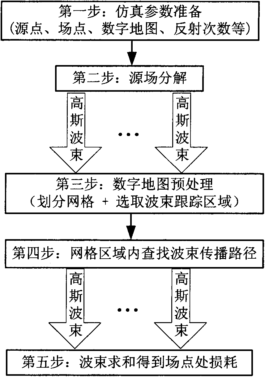
[0032] like figure 1 As shown, embodiments of the present invention are as follows:

[0033] Step 1: Prepare simulation parameters, input information such as emission source, field point, digital map, and reflection times;

[0034] Step 2: decompose the plane wave source field at the source point into a series of Gaussian beam weighted sums, the specific calculation method is shown in formula (1);

[0035] The third step: preprocessing the digital map, the specific steps are as follows: figure 2 As shown, the scene is surrounded by the smallest bounding box with a size of L*W*H, the scene is divided into equal parts by planes parallel to xOy, yOz, and zOx respectively, and the size of each grid is set to l*w*h, then M=L / l, N=W / w, K=H / h. Starting from the origin of the coordinates, which is the lower left corner of the scene, they are numbered one by one along the x-axis, y-axis, and z-axis in increasing numbers. This numbering method is convenient for quickly locating a gi...


PUM


Abstract

The invention discloses a rapid prediction method for radio wave propagation loss. The rapid prediction method comprises the steps of first enabling a plane wave source field at the position of a source point to be decomposed into the weighting sum of a series of gaussian beams; performing preprocessing on a digital map; averagely dividing a whole scene area into a plurality of grid units, enabling buildings to belong to grids where the buildings are located, enabling the grids to serve as basic units, and selecting a rectangular region covering the source point and a receiving path to serve as a beam tracking region; searching building scene propagation paths of the gaussian beams emitted from the source point in the beam tracking region; and finally performing summation of all beams reaching a field point so as to obtain loss at the position of the field point. All the beams are uniformly processed through the method, complex diffraction effect does not need considering, receiving ball processing is not involved, and arithmetic implementation is simple; a grid region joint acceleration algorithm is adopted simultaneously, the beam tracking region is minimized, collision detection time of the beams and a barrier is greatly reduced, and prediction efficiency is further improved.

Description

technical field [0001] The invention relates to the fields of radio wave propagation and computer graphics, and provides a rapid prediction method for radio wave propagation loss. Background technique [0002] With the rapid development of 4G communication, the long-term evolution technology LTE (Long Term Evolution) has attracted the attention of mainstream communication equipment manufacturers and operators at home and abroad. In the initial stage of LTE network deployment, areas with high service rates and large capacity requirements will be concentrated in urban commercial centers with dense population and buildings, which puts forward higher requirements for the accuracy and efficiency of LTE technology network planning. In network planning, the propagation model is an important factor that affects the accuracy of planning results. Accurate and efficient prediction models are of great significance for base station site selection and network optimization. [0003] At pr...

Claims


Application Information

Patent Timeline
Patent Type & Authority Applications(China)
IPC IPC(8): H04B17/00H04B17/373
Inventor 唐亚平徐大专朱秋明张小飞李小宇
Owner NANJING UNIV OF AERONAUTICS & ASTRONAUTICS
Learn More