
Spiral blade type small-size air bubble separation device

A bubble separation, rotary vane technology, applied in separation methods, liquid degassing, climate sustainability, etc., can solve the problem of inability to achieve complete gas separation, difficult to meet molten salt reactor degassing and safety requirements, unfavorable separation, etc. problems, to achieve the effect of low cost, recovery of part of the pressure energy, and reduction of maintenance costs

Inactive Publication Date: 2013-11-20
HARBIN ENG UNIV
View PDF5 Cites 14 Cited by
  • Summary
  • Abstract
  • Description
  • Claims
  • Application Information

AI Technical Summary

Problems solved by technology

At this time, if the aggregation point of the bubbles is below the zero-velocity envelope, for the separator whose overflow port is located at the inflow side of the working fluid, the gas will flow out of the cylinder together with the main flow, and the complete separation of the gas cannot be achieved.
Conversely, for the separator whose overflow port is located at the end of the cylinder, if the bubbles have already aggregated above the zero-velocity envelope, it is also not conducive to separation
Therefore, the existing technology is difficult to meet the degassing and safety requirements of molten salt reactors. It is necessary to invent a set of degassing equipment suitable for bubble separation in molten salt reactors, with high efficiency, wide working range and stable performance.

Method used


Image

  • Spiral blade type small-size air bubble separation device
  • Spiral blade type small-size air bubble separation device
  • Spiral blade type small-size air bubble separation device

Examples


Embodiment Construction

[0023] The present invention is described in more detail below in conjunction with accompanying drawing example:

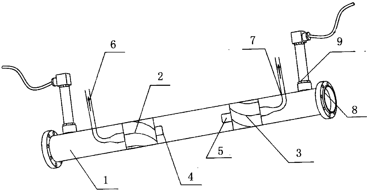
[0024] combine Figure 1~4 , the present invention comprises: cylindrical shell 1, muddy blade 2, recovery blade 3, muddy impeller shaft 4, recovery impeller shaft 5, front air outlet pipe 6; rear air outlet pipe 7, flange plate 8 for connecting with pipeline and pressure sensor9. The mixing blade 2 and the mixing impeller shaft 4 in the center form the mixing impeller, which is located at the front end of the cylinder 1. The center of the mixing impeller shaft 4 has a hole and is connected with the front outlet pipe 6 for leading out the separated gas; the recovery blade 3 and its center The recovery impeller wheel shaft 5 forms the recovery impeller, which is located at the rear end of the cylinder body 1. The center of the recovery impeller wheel shaft 5 is opened and connected with the rear air outlet pipe 7, which is also used for deriving the separated gas;...


PUM


Abstract

The invention aims to provide a spiral blade type small-size air bubble separation device which comprises a cylindrical barrel body, wherein a front air discharging pipe is arranged at the front end of the barrel body; a rear air discharging pipe is arranged at the rear end of the barrel body; a stirring blade wheel and a recovering blade wheel are respectively arranged in the barrel body; the stirring blade wheel comprises stirring blades and a stirring blade wheel shaft; the recovering blade wheel comprises recovering blades and a recovering blade wheel shaft; center holes are formed in both the stirring blade wheel shaft and the recovering blade wheel shaft; inlets of the two center holes are opposite; an air outlet of the center hole in the stirring blade wheel shaft is communicated with the front air discharging pipe; an air outlet of the center hole in the recovering blade wheel shaft is communicated with the rear air discharging pipe. The spiral blade type small-size air bubble separation device can realize the high-efficiency separation of small air bubbles and can work in a wide air content range and a wide liquid flow range; the recovering blade wheel at the tail has a function of partially recovering the pressure, so that the power investment in the equipment running process is effectively reduced, and the equipment running cost can be reduced.

Description

technical field [0001] The present invention relates to a separation device, in particular to a bubble separation device. Background technique [0002] There are more than 900 types of reactors and conceptual reactors at home and abroad. Molten salt reactors have gained the attention of nuclear science experts and scholars again after several years of silence due to their high safety and closed fuel cycle advantages. During the operation of lava reactors, fission gases with relatively large neutron absorption cross-sections, such as xenon and krypton, will be continuously produced. Their existence seriously affects the operation of the reactor, and even leads to shutdown, and is regarded as a poison in the reactor. In addition, these inert gases exist in the form of bubbles in the molten salt. With the operation of the reactor, they accumulate and increase. If they are not removed in time, they will also affect the heat transfer characteristics of the reactor. Therefore, it...

Claims


Application Information

Patent Timeline
IPC IPC(8): B01D19/00G21C19/303
CPCY02E30/30
Inventor 张娜娜孙立成阎昌琪唐文偲蔡报炜孙中宁曹夏昕王建军范广铭丁铭
Owner HARBIN ENG UNIV
Learn More