A torque transfer device connected with a torque converter with the aid of gear engagement

A technology of torque converter and torque converter housing, applied in the field of drive train, to achieve the effect of miniaturized cost, less axial installation space, and compact structure

Active Publication Date: 2013-11-20
SCHAEFFLER TECH AG & CO KG
View PDF12 Cites 2 Cited by
  • Summary
  • Abstract
  • Description
  • Claims
  • Application Information

AI Technical Summary

Problems solved by technology

[0014] However, the known embodiments using threaded connections have the disadvantage that in the case of axial threaded connections, a considerable amount of installation space must be reserved radially above the torque converter for bolts and tools and / or in the case of axial and radial threaded connections. When connecting, a possible additional clearance must be provided in the torque converter housing for the run-in bolts and tools

Method used


Image

  • A torque transfer device connected with a torque converter with the aid of gear engagement
  • A torque transfer device connected with a torque converter with the aid of gear engagement
  • A torque transfer device connected with a torque converter with the aid of gear engagement

Examples


Embodiment Construction

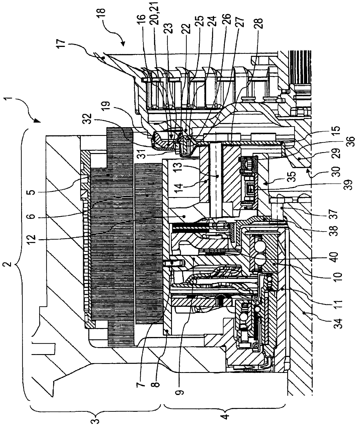
[0035] figure 1 A detail of a drive train 1 according to the invention is shown. Such a drive train 1 according to the invention is used in a motor vehicle, such as a passenger car or a truck, which uses both an internal combustion engine (not shown) and a hybrid module 2 comprising an electric machine and a converter assembly.

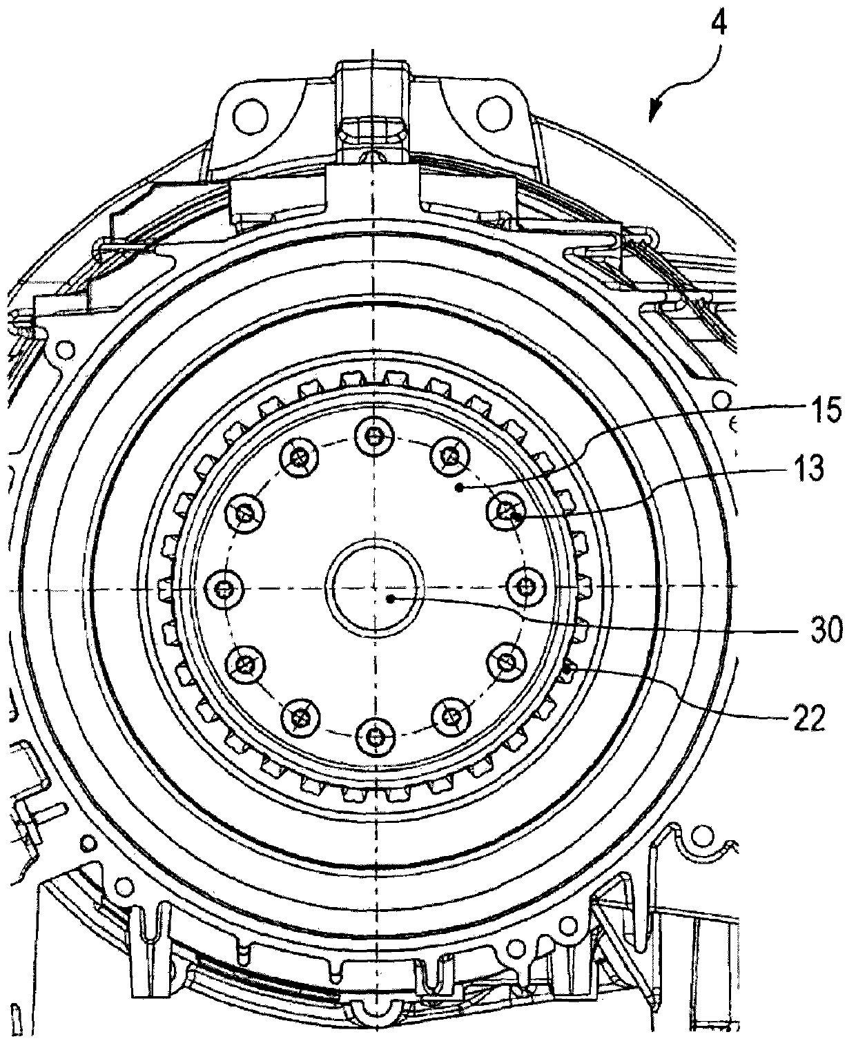
[0036] An electric machine designed as an electric motor is designated with reference numeral 3 . The switching assembly has the reference numeral 4 and is designed as a clutch.

[0037] The electric machine 3 has a stator 5 and a rotor 6 . The rotor 6 is connected to the tubular member 8 by pins 7 . The tubular member 8 is supported on a central bearing 10 via a connecting flange 9 . The central bearing 10 is designed as a roller bearing. The central bearing 10 is inserted into a sleeve-shaped member 11 which is part of the operating system of the conversion assembly 4 .

[0038] The torque generated by the electric motor 3 is transmitted via ...


PUM


Abstract

The powertrain (1) has a hybrid module (2) that is provided with an electric machine (3). A circuit unit (4) is provided between an internal combustion motor-driven flange (34) and a gear box-tied up transducer (18). The circuit unit is provided to decouple electric machine by flange. The hybrid module is provided with a transducer through a gear (20).

Description

technical field [0001] The invention relates to a drive train for a motor vehicle, such as a passenger car or a truck, between an internal combustion engine and a transmission, wherein a hybrid module comprising an electric machine and a converter assembly is located between a flanged shaft capable of being driven by the internal combustion engine and a Connected between the torque converter of the transmission, wherein the conversion assembly is also configured to decouple the electric motor from the flange shaft. [0002] An electric motor is also to be understood as an electric motor, while a separating clutch is also included in the converter assembly. Mix modules can also be described as mix heads. [0003] The invention also relates to the connection of the compression ring between the hybrid module and the torque converter. Background technique [0004] Related prior art is known from the documents WO 2007 / 000131 A2, WO 2007 / 118449 A2, EP 1 347 210 B1 and DE 100 36 ...

Claims


Application Information

Patent Timeline
Patent Type & Authority Applications(China)
IPC IPC(8): B60K6/40B60K6/50B60K6/48
CPCB60Y2304/01B60K6/383F16H2045/002B60K6/40B60K6/48Y02T10/6221B60Y2304/07F16H41/24F16H57/025F16H2057/02034Y02T10/62
Inventor W·鲁德S·马科维亚克
Owner SCHAEFFLER TECH AG & CO KG
Why Eureka
Try Eureka